- Posts
- 16,482
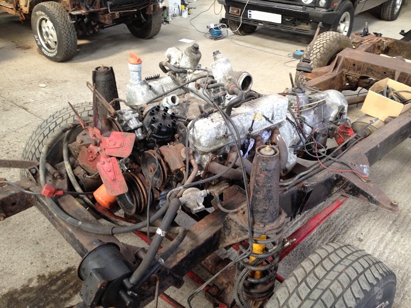
Adam kindly asked if I could give him a hand with the removal and rebuild of the 44 year old (as of 2015) Suffix A Range Rover Classic engine.
I have stripped a few V8’s before and a couple of carb models, but this is one of the earliest Classic engines I have been privileged to work on and, unfortunately the most seized…..
This could be either an triumphant win or an epic fail…..can this 44 year old seized, corroded V8 come back to life???
Lets start at the beginning…..Adams thread….
https://www.landyzone.co.uk/land-rover/suffix-a-and-csk-restoration.286717/
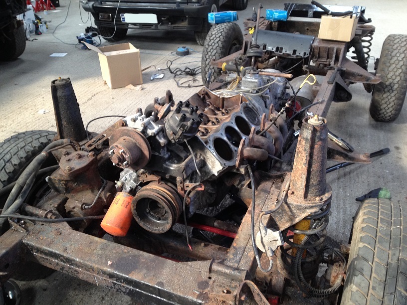
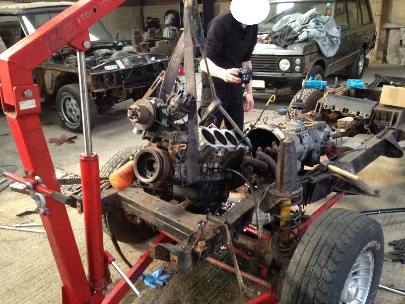
I have to say, getting the engine out with the whole body off is a fecking dream, no cramped spaces, easy access to everything, brilliant!
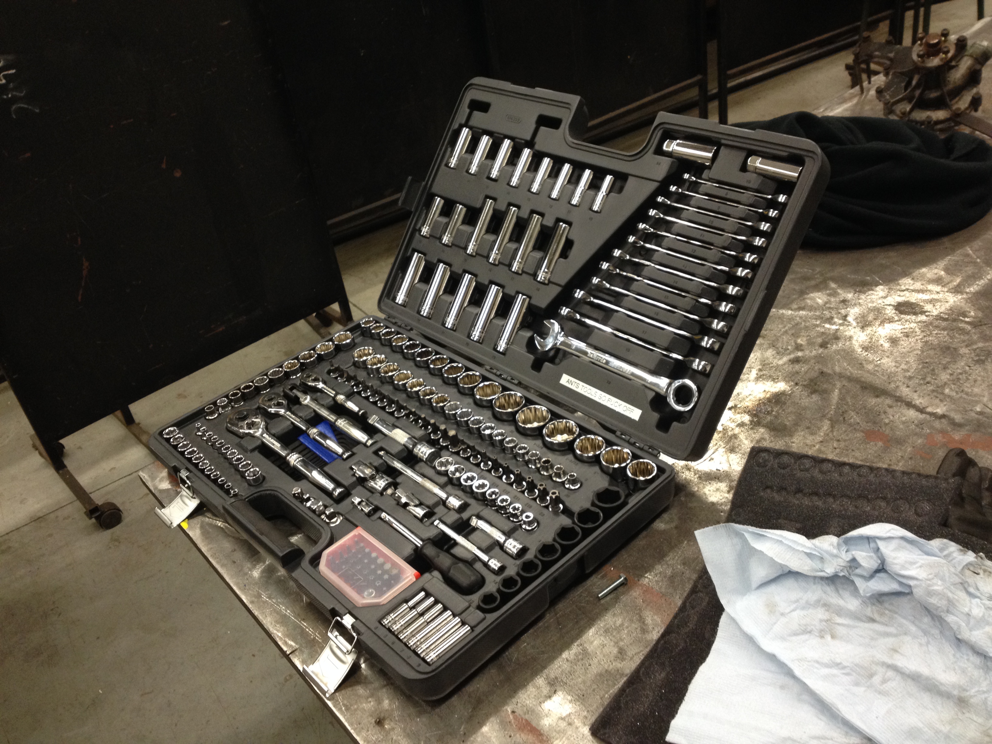
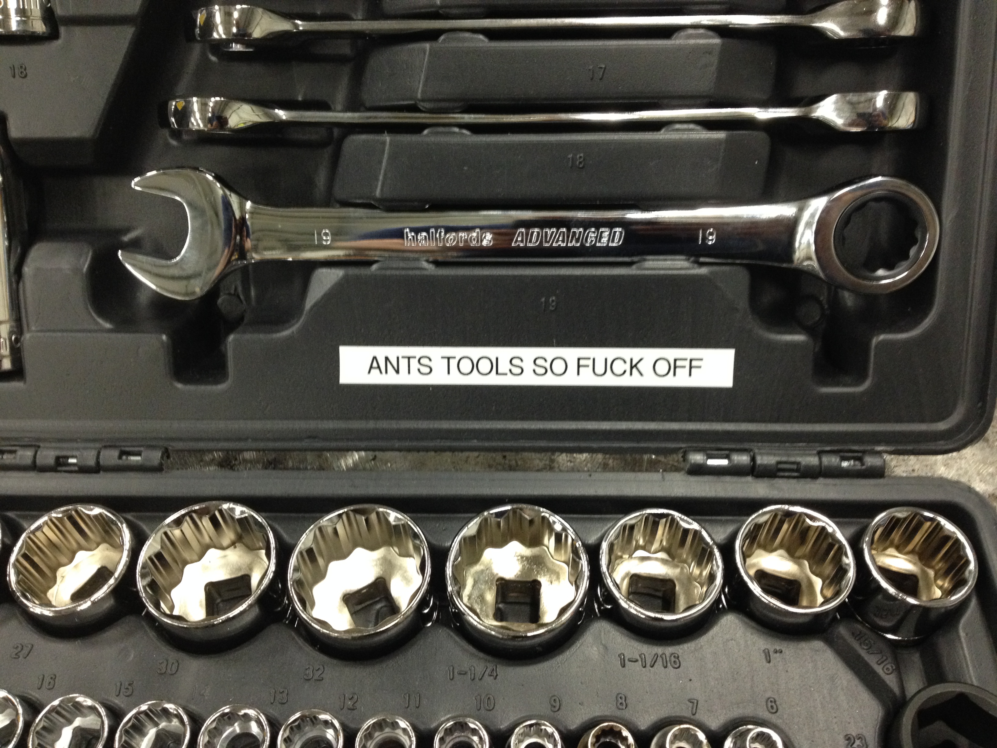
I always advocate having a good selection of tools to hand, I have a red tool chest of tools, sockets, spanners, odd tools made or acquired over the years, and is very much my go to set for 90% of the work I do, but on special occasions I pull out my £300 Tool Set complete with warning message as these sockets or seldom used, dropped or abused, they are perfect for any stubborn nut or bolt I may encounter….
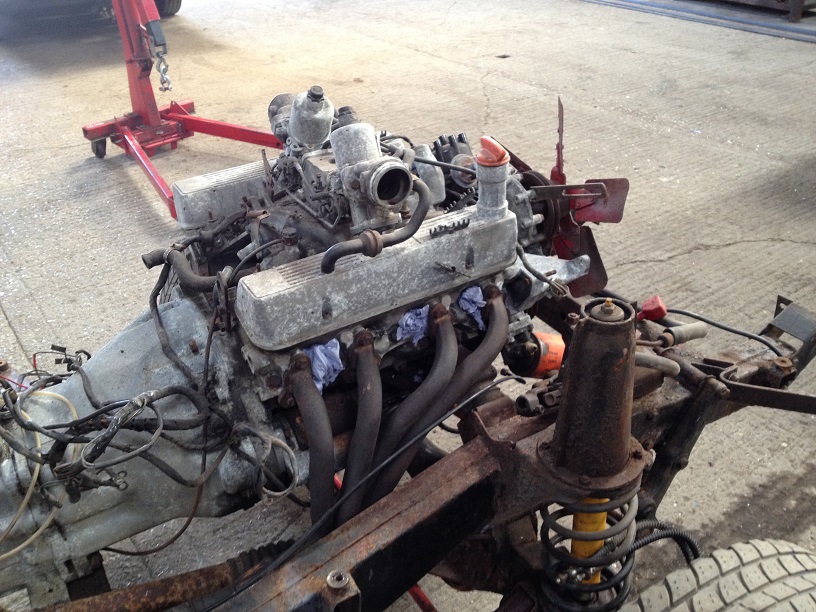
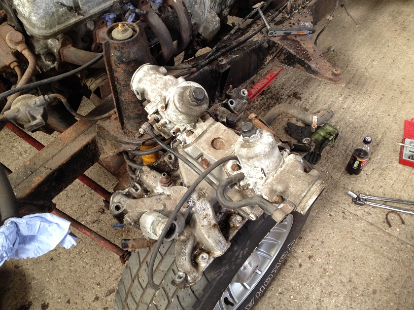
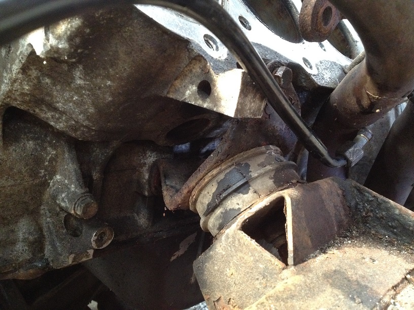
With Adams help we stripped off the exhaust headers and inlet manifold.
Simple enough to do, disconnect throttle linkage, fuel pipe to carbs, rocker breathers to intake manifold, small pipe from back of water pump to inlet manifold and the other pipe from the other side of the manifold to the heater.
With a bit of a gentle pry the inlet manifold pops off….
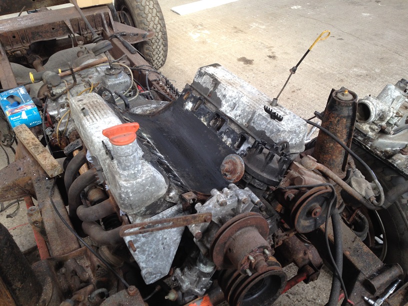
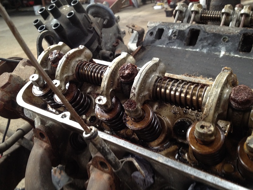
Undo the 4 screws (each) on the rocker covers and remove. Pleasantly surprised considering the age and condition of the engine that the rocker space was really clean. There were rust deposits on the bolts and push rods, but other than that it was really clean and has obviously been looked after before it was laid up for 10 years and seized.
Now here is the odd thing….. Suffix B engines are meant to have the oil pump drive from the crank and ‘without the B suffix’ engine number from the bottom of the dizzy…. ‘With a B’ engines only use 2 rows of head bolts and those ‘without the B suffix’ engine number use 3 rows.
This engine is a B suffix but the oil pump is driven from the dizzy and has 3 rows of head bolts…..so I can only assume if it is the original block, that it is a very early B suffix.
Any-how, time to see what lurks under the heads….
Now, if you are removing the engine normally it all stays on and lifted out as a lump as the heads have the lifting points, but I suggested will pull the heads so Adam could see inside and also as the body is off, slinging the engine without the heads isn’t too difficult as you can get the slings under the engine easy enough with no body panels in the way.
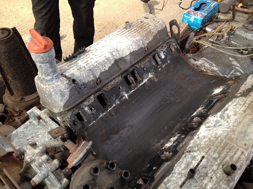
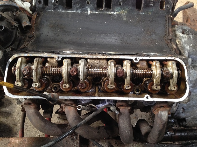
Undo the bolts forking from the centre outwards in a spiral pattern (follow RAVE).
With a light tap from a rubber faced mallet, the heads lift off. Note, they are doweled so don’t be trying to launch them sideways, just a love tap to crack the seal, and lift upwards.
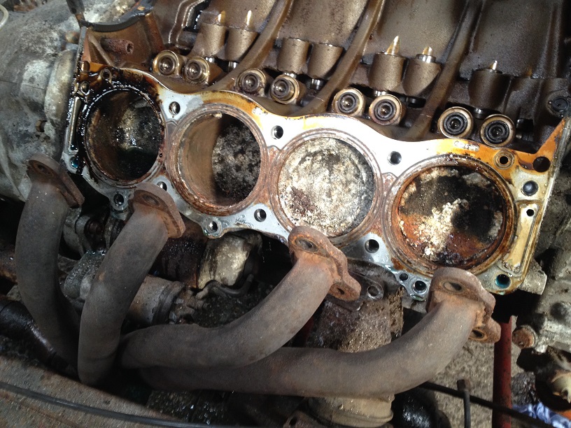
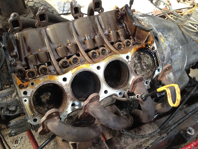
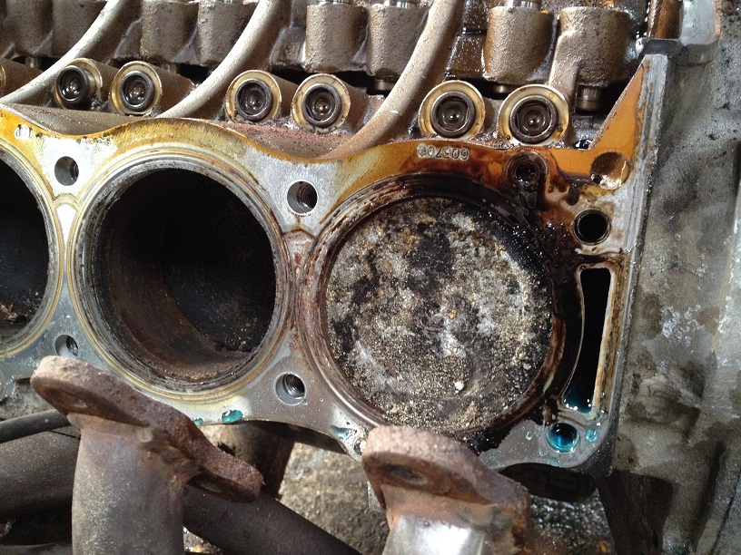
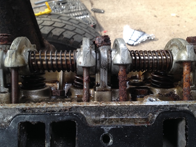
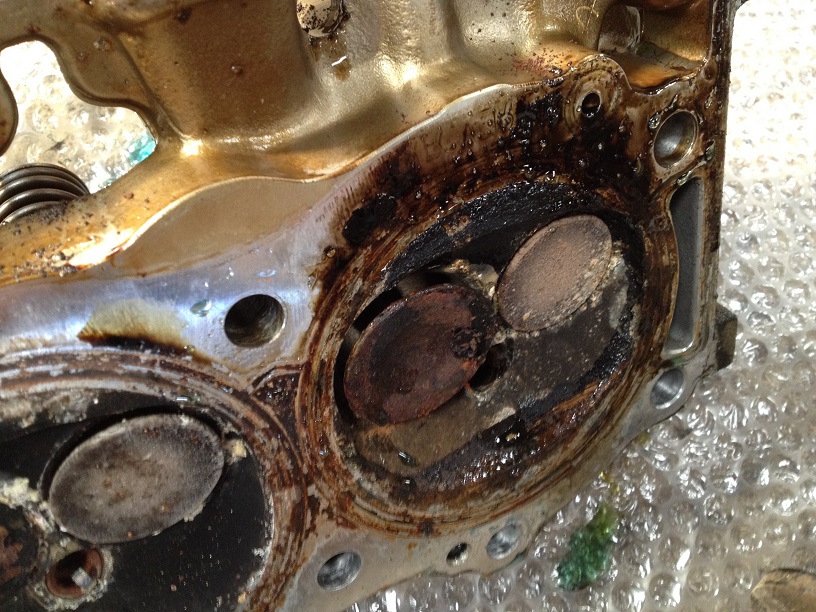
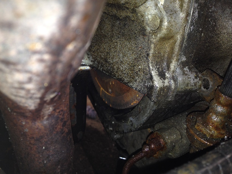
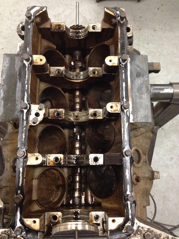
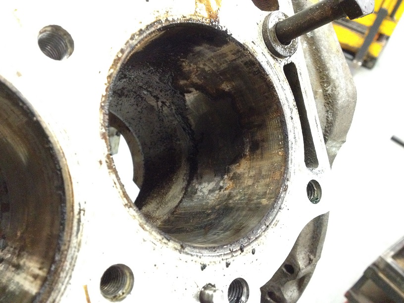
Looking a bit nasty and corroded in there…no wonder it is seized solid….
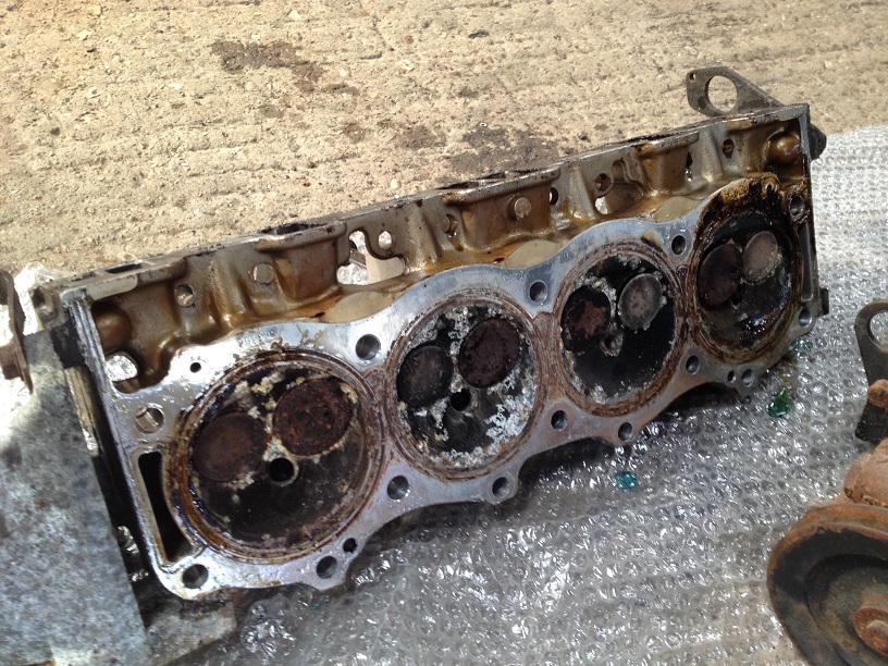
The Right Hand Head had two valves stuck open, so looks like new valves, stems and seal as a minimum…
Time to free the engine….
Climb underneath and remove the fly wheel/bell housing cover plate
Using a jack and block of wood, support the gearbox
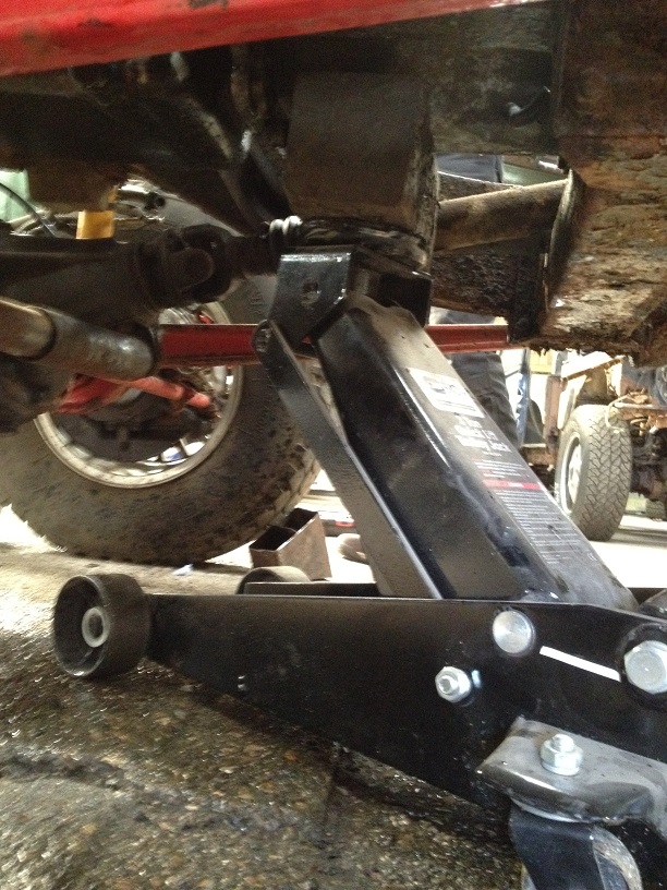
Remove the bell housing bolts, but leave the top two in for the moment.
Sling the engine carefully to avoid placing stress on any fragile components.
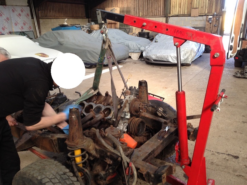
Take a bit of strain on the crane and start to undo the engine mounts from the block
Double check the rigging and strain on the straps and then remove the last two bellhousing bolts. Start to gently lift the engine a few mm, then pull the crane away slightly and pop the bellhousing from the engine. This is doweled too, so dn’t lift the engine to high or bash the bellhousing up or down.
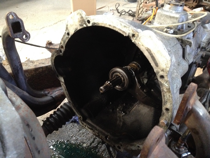
With a jiggle, they will slide apart, slowly pull the engine forward to slide the gearbox input shaft from the clutch/flywheel.
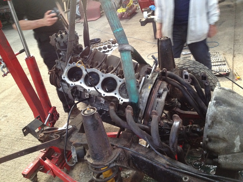
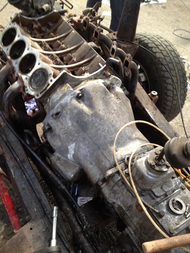
Next is a bit tricky, you have to lift the front of the engine up at an angle to clear the front chassis cross member….easiest way is to use an adjustable lifting beam (about £40) but with a tremendous amount of luck, we had slung the engine almost perfectly to naturally sit at this nose high angle!
Gearbox input shaft spines, bearing and clutch fork looks in near perfect condition, even the grease on the components was still the golden grease colour!!
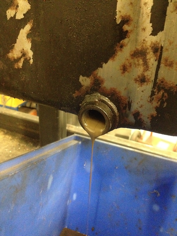
Drained the oil and strapped to a pallet.
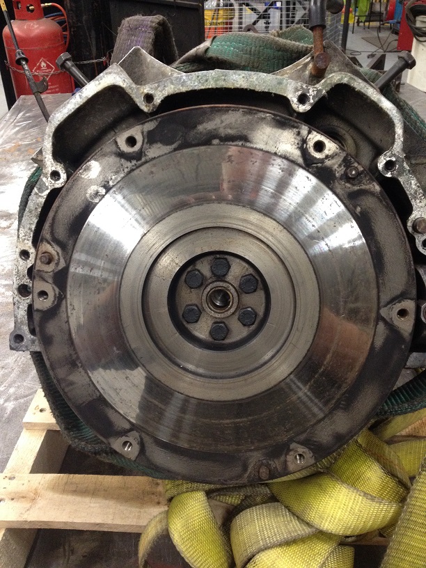
Back at the workshop, as the crank is seized solid it makes it easy to undo the flywheel bolts, before removing the flywheel, mark its position to the crank.
The Clutch surface looks spotless and there is no ridge on the edge, so has been well driven and looked after previously!
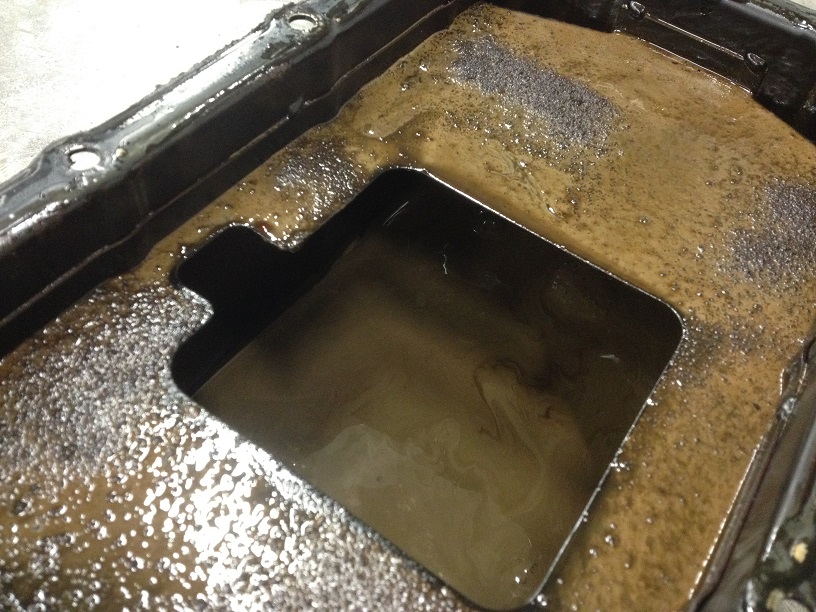
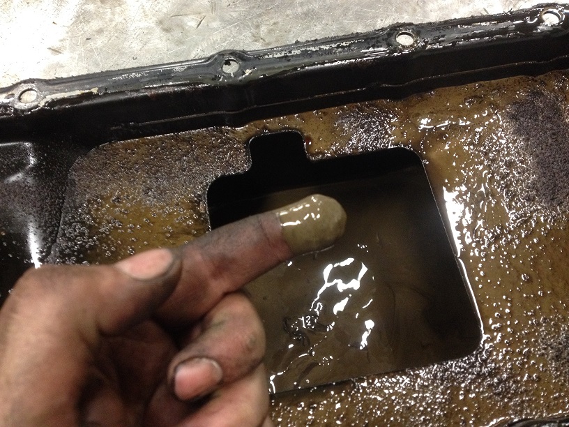
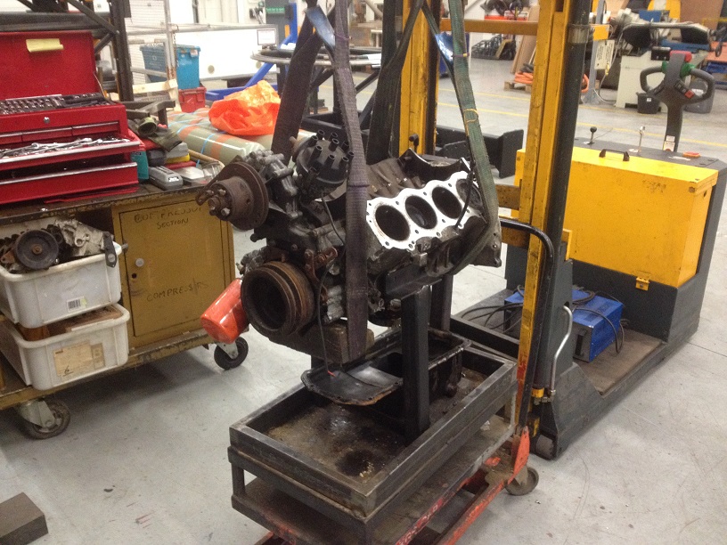
Knocked up a temporary stand to seat her on and dropped the sump, glad that as this point I hadn’t put the block on the rotating stand I was building and turned I upside down, as the sludge in the bottom of the Sump Pan was errr…about and inch thick with emulsified oil, water, gunge, carbon etc….nice!
Left her on this temp stand since Sunday until Thursday with the bores filled with a 50/50 mix of Hypersolve (we aren’t allowed Acetone at work – to flammable – but we are allowed Acetylene and Oxygen gas….go figure) and Dexron III ATF…..
Best is Diesel, but that’ll stink out the workshop and the boss won’t be too happy with me….so this is the next best thing……
Acetone or other solvent cleaner will start to attack the deposits that are sticking the pistons to the liners, and the ATF is a great lubricate, detergent and penetrant…able to soak in and even run up through capillary action….good stuff.
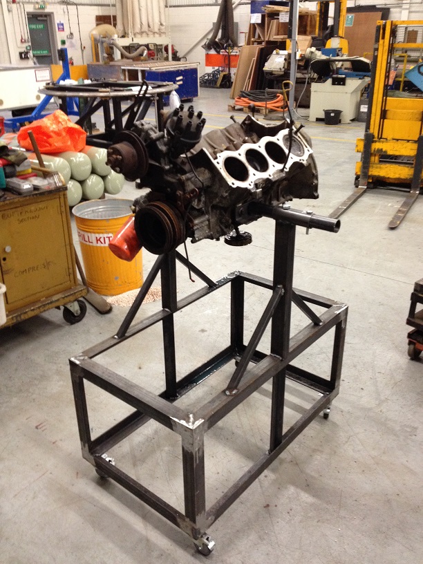
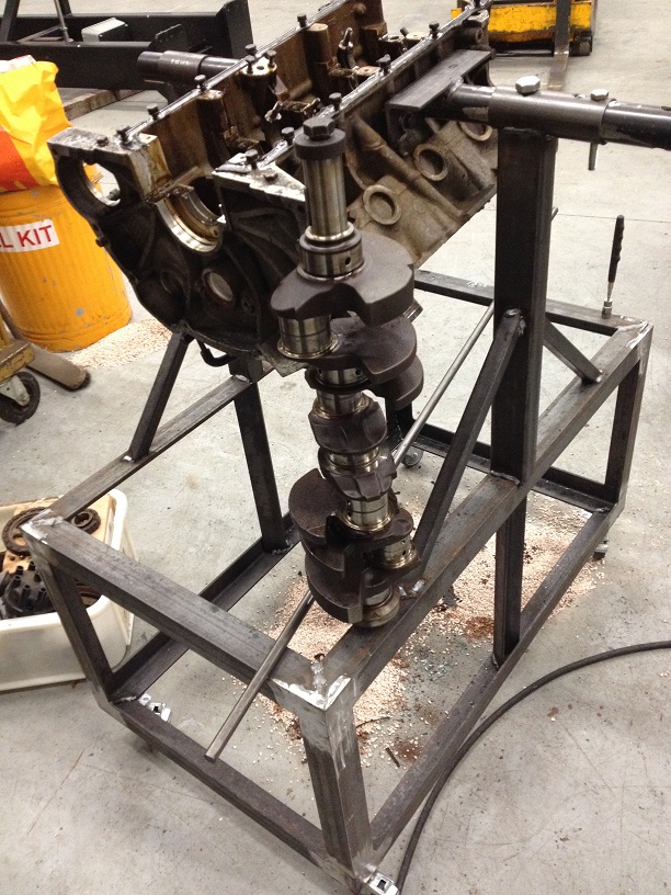
Rotating stand almost finished
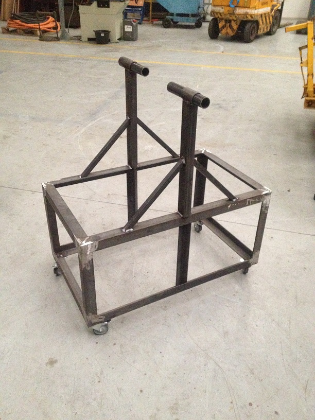
I am not a fan on the rear mounting stands…..too much leverage action on the bellhousing for my liking, so this bolts to the side mounts which are designed to support the engine weight in the first place!
Making the lift from one to the other….

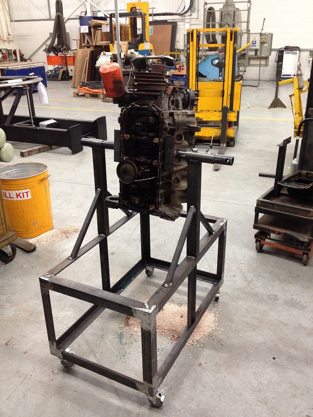
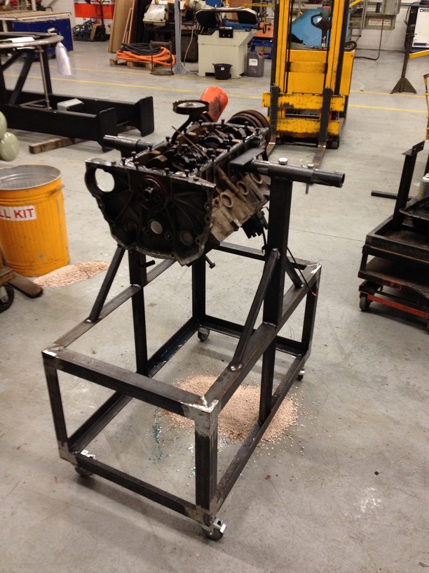
Now able to rotate and station the engine top side up, upside down and on its end, the task of stripping the block can start.
Again as the crank is solid, removing the crank bolt was simple enough….I will be looking to make a holding tool for the refit!
Noticed this little sticker on the side of the timing cover….
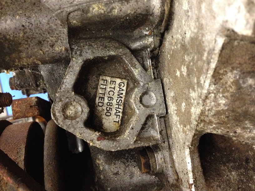
Which indicates the correct Cam for the 8.13:1 Compression Ratio engine, which this one is!
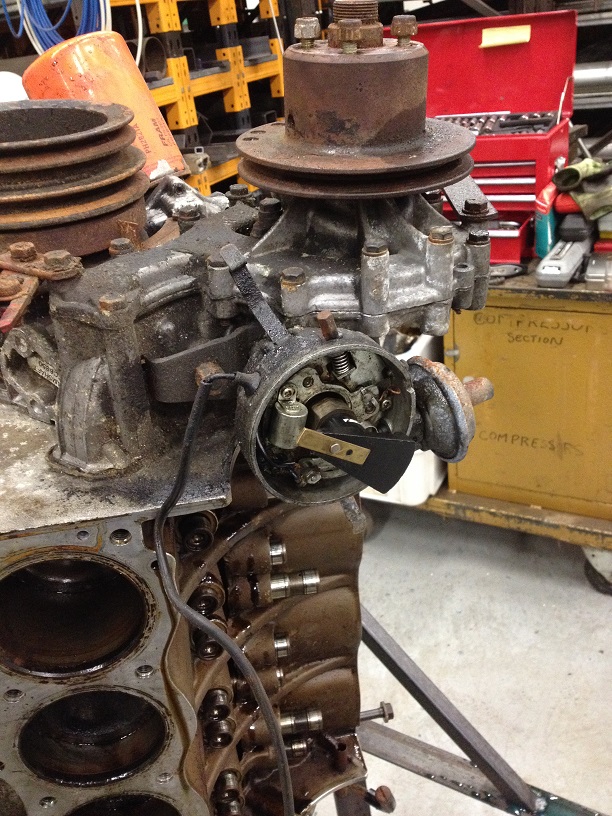
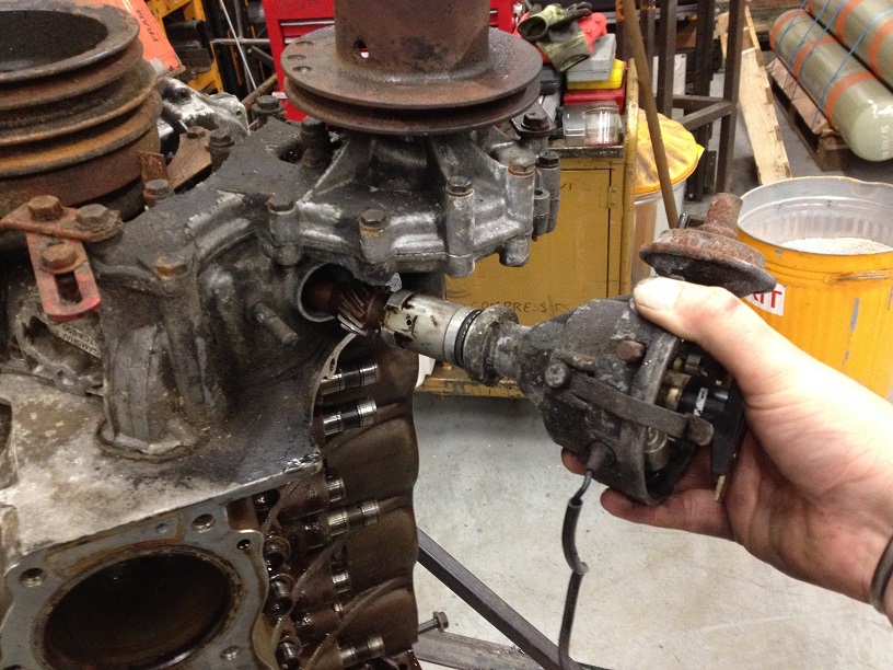
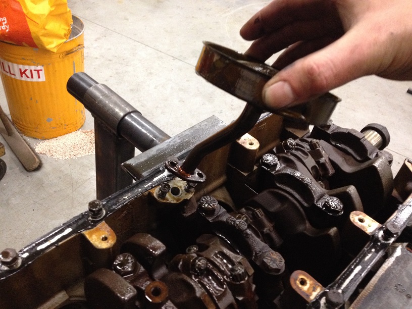
First off, remove the dizzy…..mark its position for referenceand undo the clamp to withdraw (with a tug) from the timing cover….DO NOT pull on the rotor as you can dislodge the bobweights in the advance mechanism.
Unbolt the water pump – Note some bolts are longer than others and also are different head sizes (as these ones also go into the block!)
Very clean underneath the pump, as the corrosion inhibitors in the fresh coolant have done their job (another reason to keep yer cooling system fresh!)
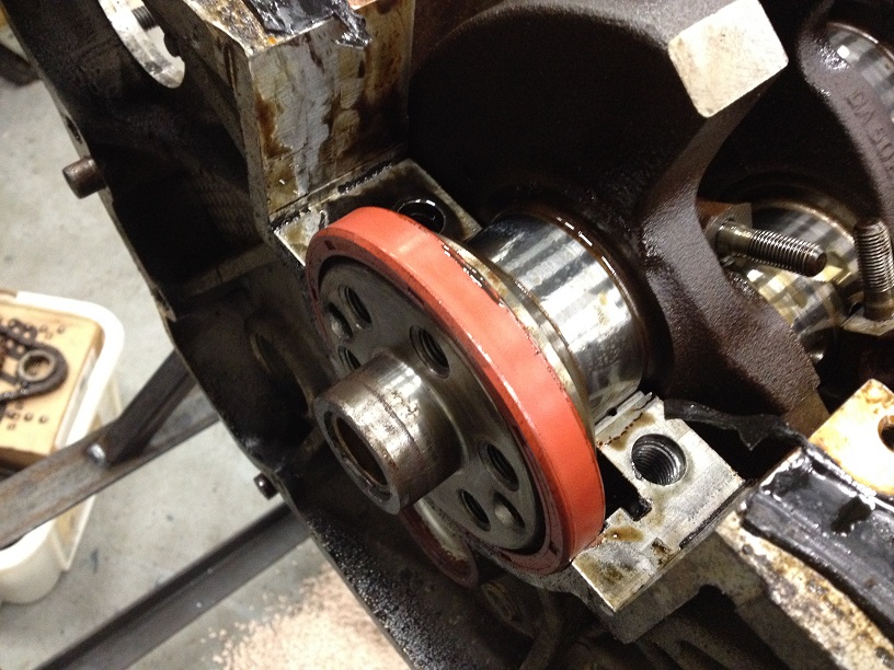
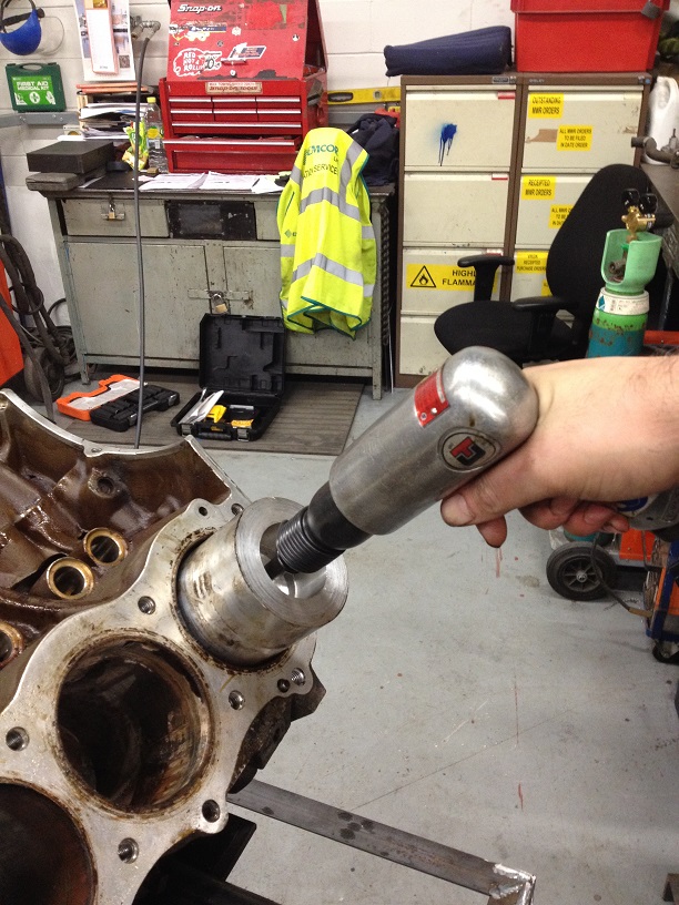
Remove the crank pulley and damper assembly….this can be tight on the shaft so a puller is required, this one was just a little wiggle and off she came!
Remove the old oil filter, tried the chain wrench, but this filter was done up tight! So out came the more persuasive tool…..
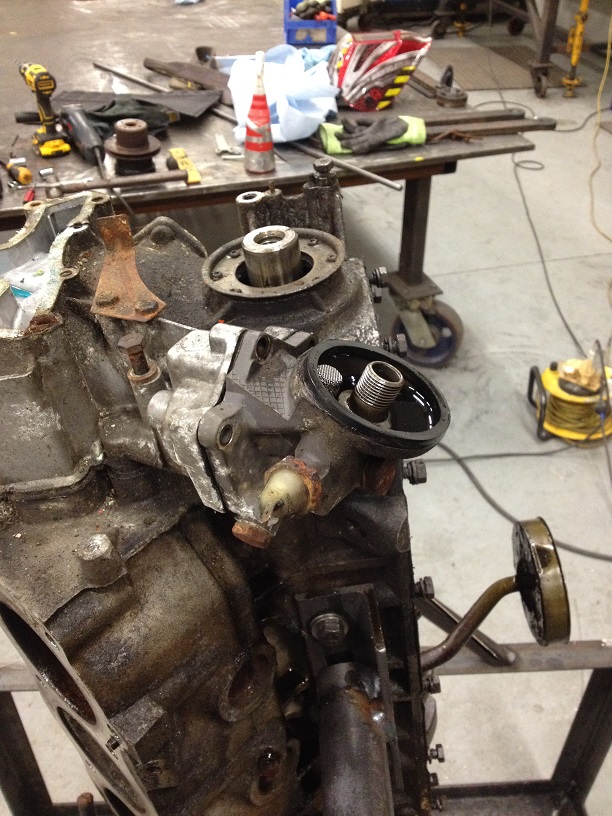
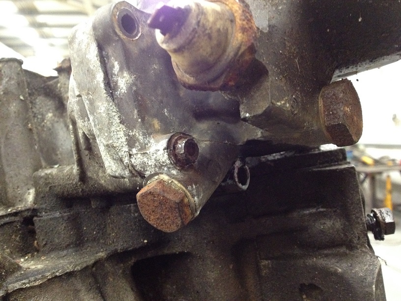
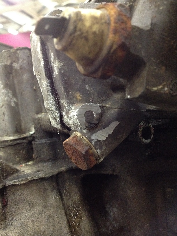
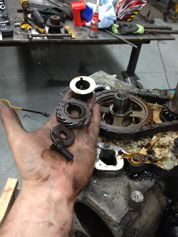
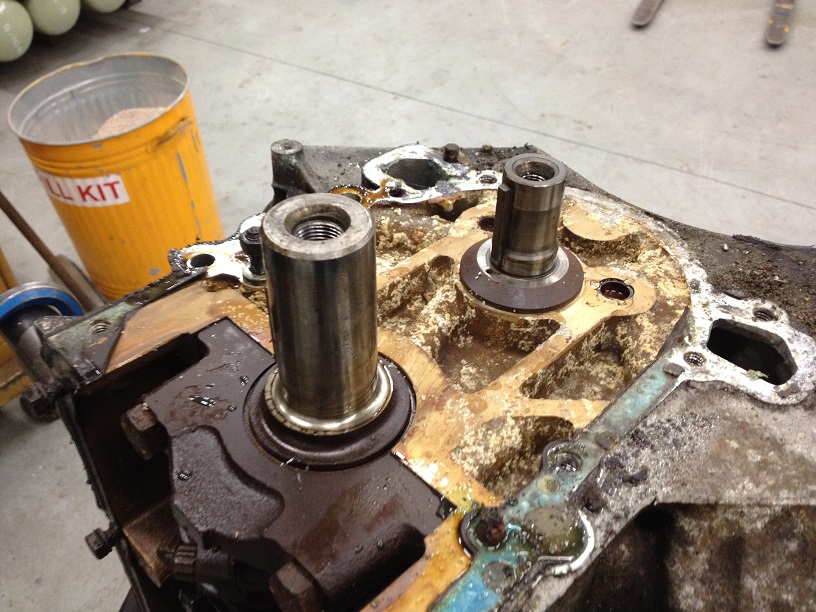
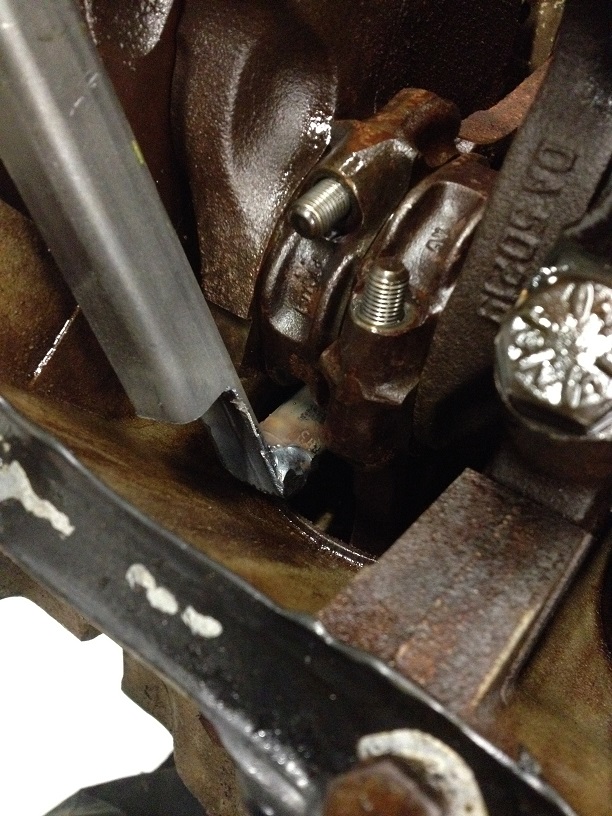
Next is to remove the oil pump drive housing as one of the cover bolts sits under this. All but one bolt came off, this little fecker was rusted and rounded off, so unfortunately I had to cut this one off and then I will get the stud out later.
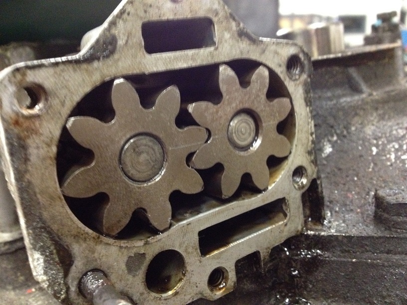
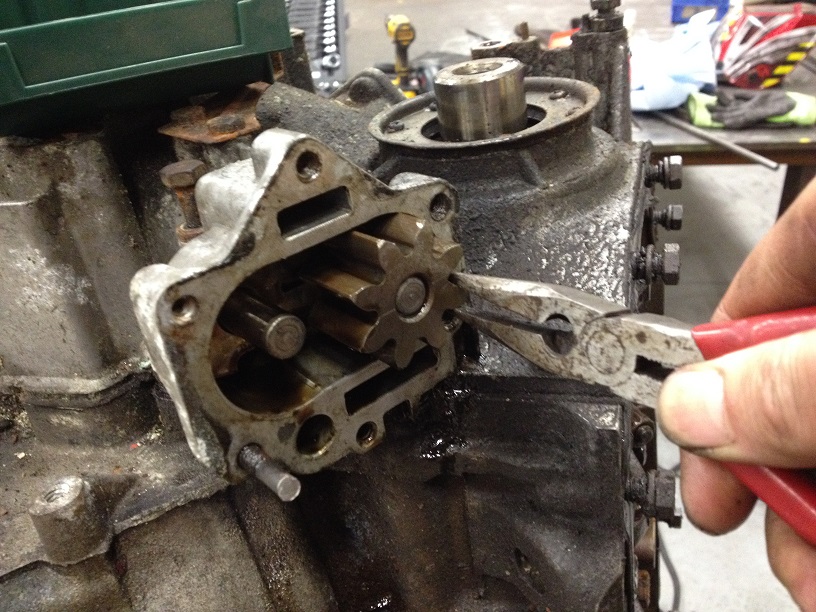
Mark the oil pump gears in relation to each other (as over time the teeth wear to match their meshed opposite and work more efficiently) and carefully withdraw from the housing….stuff rag into the housing for protection of the machined faces of the pump.
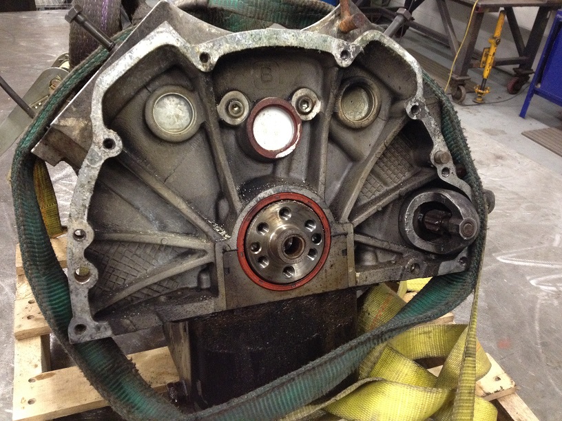
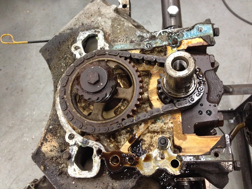
So undo all the remaining timing cover bolts and remove the cover. Underneath the cover shows some more lovely corrosion. Mainly aluminium oxide dust, will see how well it cleans up.
Again, as the crank is locked up, removing the camshaft bolt was simple enough….
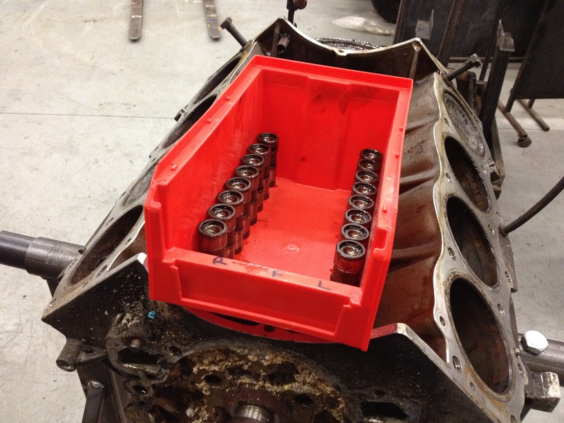
Pull the hydraulic lifters out and keep in cylinder order. Submerge them in fresh engine oil (these ones will be soaked and pumped up prior to refit as they show very little wear, as does the camshaft)
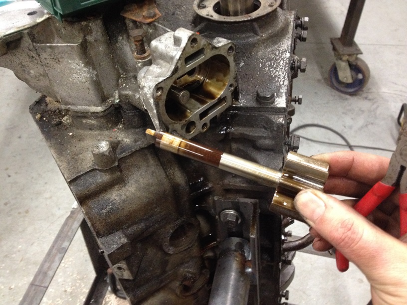
Withdraw the dipstick tube….
Flip the engine over and remove Oil Pick Up…..
Now the fun can begin!!
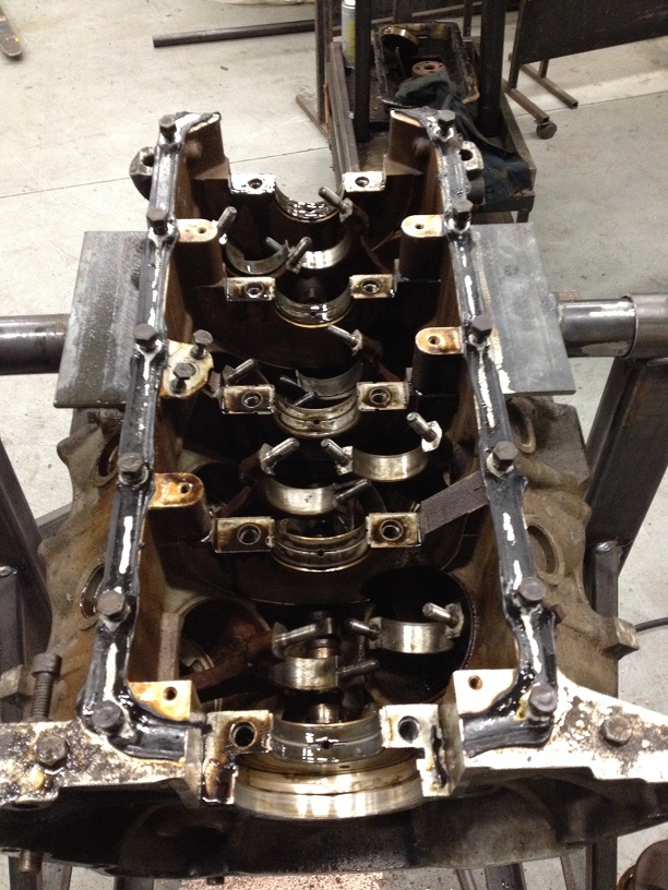
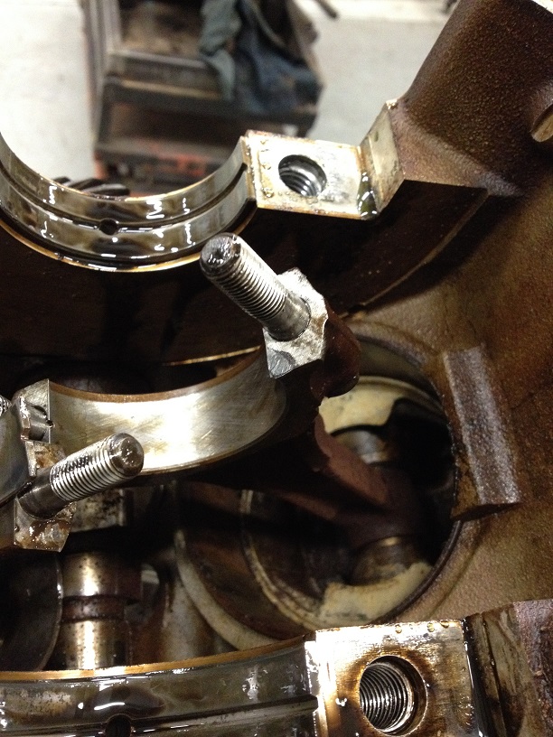
Time to remove the con rod caps in a bid to free the crankshaft. As can be seen some of the cap bolts are buried down close to the side of the block with no space for a spanner or ratchet….a deep angled ring spanner might have reached, but I don’t have any of those (now on order btw!!) so I made a substitute from a 1/2” bi-hex socket welded to a bit of box section with the back cut off to fit down next to the block….
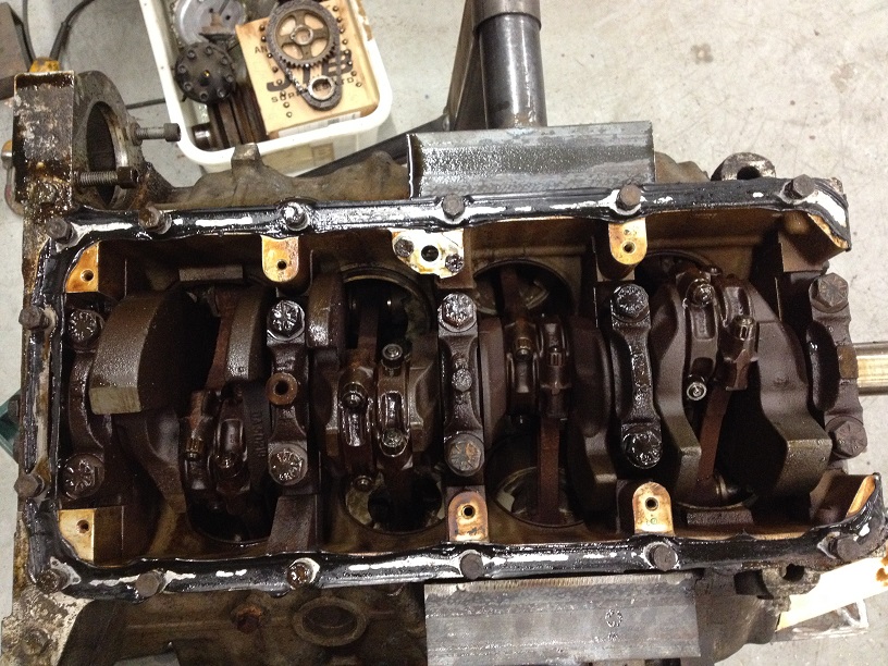
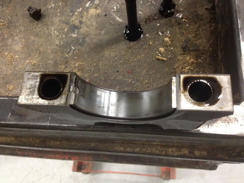
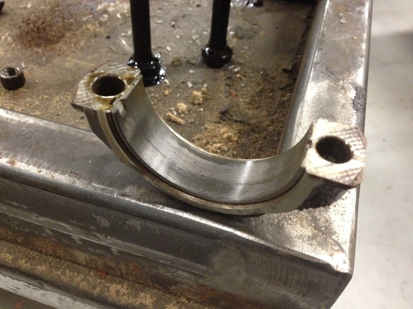
Remove the crank bearing caps and keep in order. The rear cap has a seal down the sides and sealant at the base, so can be a tight little fart to get out.
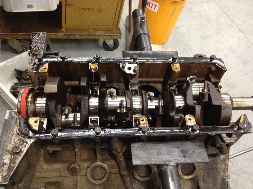
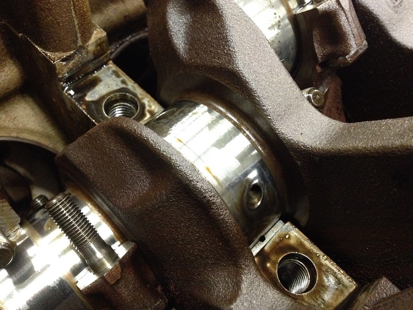
Crank journals look in great condition too, as are the bearing shells from both the crank and con rods!!
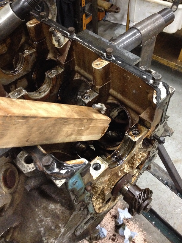
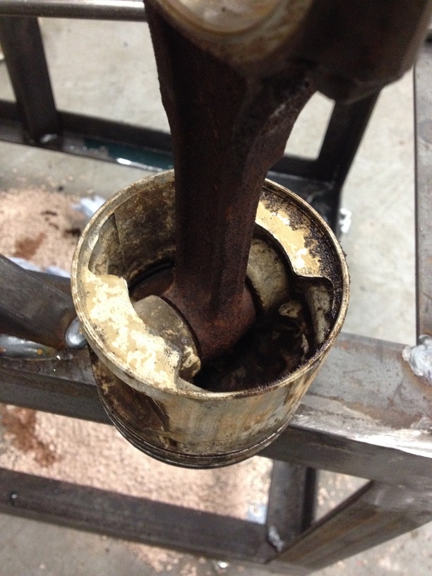
Hoping I could then lift the crank out were thwarted by the fact the Gudgeon pins in the pistons are seized solid and the con rods wouldn’t move to the side as the crank was lifted….
I had to get pistons to move to get the crank out….
So, a couple of crank caps back on, and flipped the engine over.
Machined up an aluminium drift to sit on the piston crown, and using a reaction riveting gun, applied vibration to the piston to try and crack any deposits holding the piston in place. Then flipped the engine back over, and using a drift started knocking the piston down the bore. Unfortunately the only place available to drift from was the ends of the con rods, and in some cases of the really stubborn pistons, there is small burring on the end of the rod, hopefully we’ll be able to clean these up later.
With them move down sufficiently the crank can be lifted out!
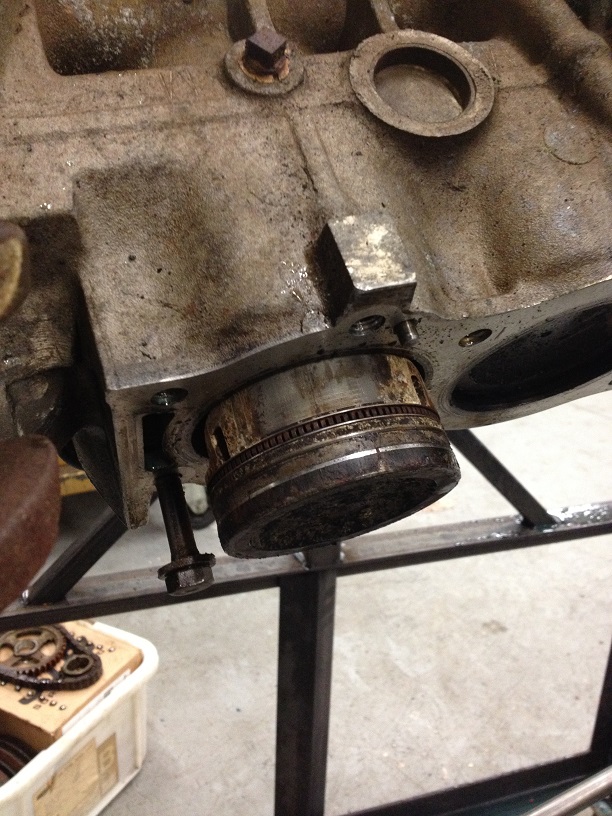
Using the vibrate method, I move each piston to the bottom of the bore, cleaned out the crap from above the piston on the bores, then using a block of wood, drifted the pistons back out again….
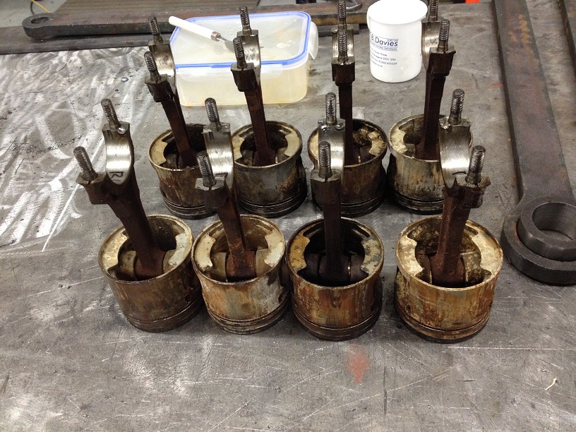
Mark each piston assembly with its location once removed.
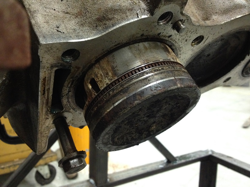
Pistons are dirty and corroded, the gudgeon pins are seized solid, so I will soak them all in a 50/50 mix of solvent and ATF again for a few days and see if I can get the pins to move!
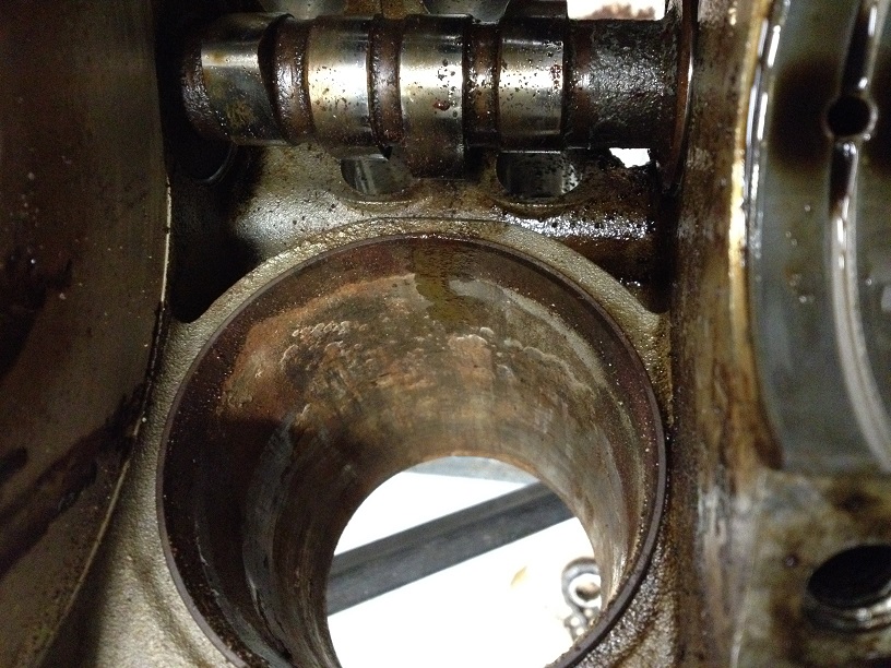
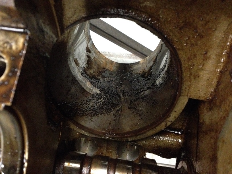
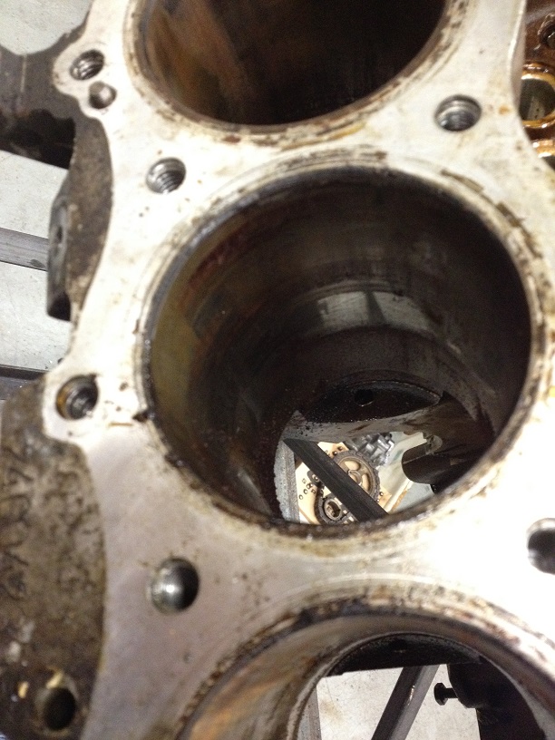
Block with the pistons out….bores look a little messy, but after a brief clean I think it just requires elbow grease, paitience and once the heavy deposits are out, the stubborn ones will move with the honing stones!
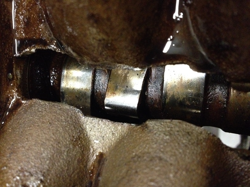
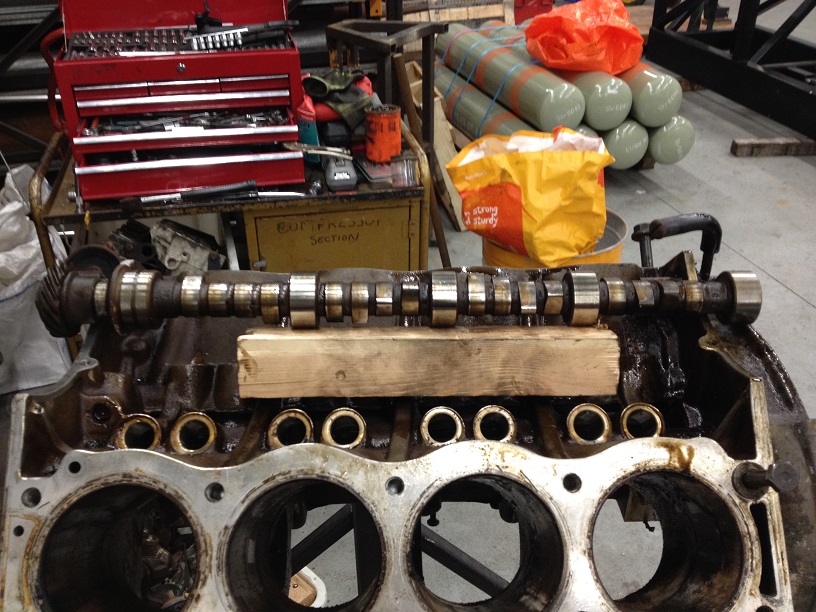
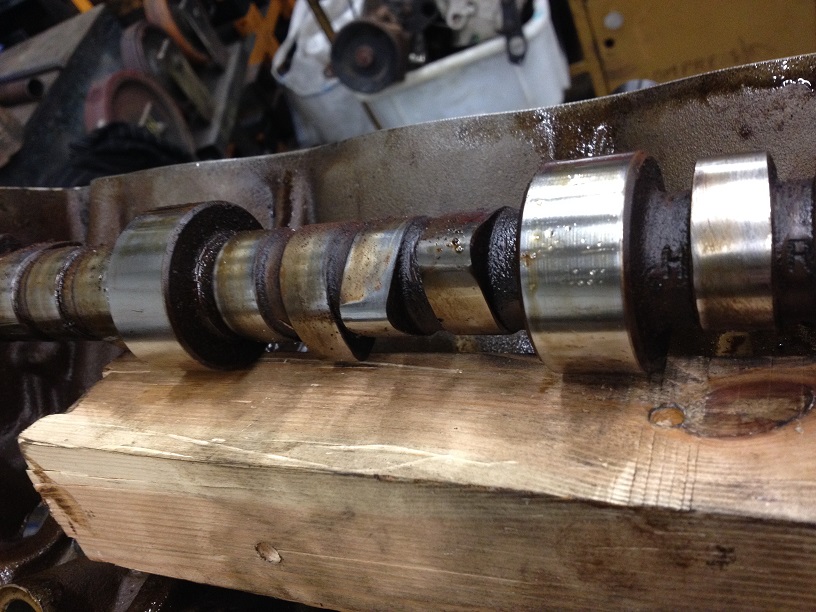
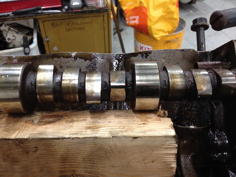
Carefully withdraw the camshaft (this can be done once the timing chains are off, but for an un-known reason I left it in the block…..excitement to get the pistons out I think…..if you have left it in, as you rotate the engine, you have to be mindfull not to let the engine go nose down else the cam will slide out!
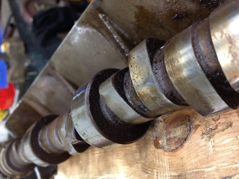
Cast on the side of the cam is a number. Not sure this is a part number or casting number as no details are listed under this reference HRC1619 so I can only assume it is the number of the cast used to forge the cam!
So, now we have a bare block and a couple of boxes of bits!
First thing to do is clean the bores, if they can be cleaned up without needed to bore them out, happy days, then everything can proceed…..there is little point in doing anything else until we can see if the block can be saved first…..that’s the next instalment!
I have stripped a few V8’s before and a couple of carb models, but this is one of the earliest Classic engines I have been privileged to work on and, unfortunately the most seized…..
This could be either an triumphant win or an epic fail…..can this 44 year old seized, corroded V8 come back to life???
Lets start at the beginning…..Adams thread….
https://www.landyzone.co.uk/land-rover/suffix-a-and-csk-restoration.286717/
I have to say, getting the engine out with the whole body off is a fecking dream, no cramped spaces, easy access to everything, brilliant!
I always advocate having a good selection of tools to hand, I have a red tool chest of tools, sockets, spanners, odd tools made or acquired over the years, and is very much my go to set for 90% of the work I do, but on special occasions I pull out my £300 Tool Set complete with warning message as these sockets or seldom used, dropped or abused, they are perfect for any stubborn nut or bolt I may encounter….
With Adams help we stripped off the exhaust headers and inlet manifold.
Simple enough to do, disconnect throttle linkage, fuel pipe to carbs, rocker breathers to intake manifold, small pipe from back of water pump to inlet manifold and the other pipe from the other side of the manifold to the heater.
With a bit of a gentle pry the inlet manifold pops off….
Undo the 4 screws (each) on the rocker covers and remove. Pleasantly surprised considering the age and condition of the engine that the rocker space was really clean. There were rust deposits on the bolts and push rods, but other than that it was really clean and has obviously been looked after before it was laid up for 10 years and seized.
Now here is the odd thing….. Suffix B engines are meant to have the oil pump drive from the crank and ‘without the B suffix’ engine number from the bottom of the dizzy…. ‘With a B’ engines only use 2 rows of head bolts and those ‘without the B suffix’ engine number use 3 rows.
This engine is a B suffix but the oil pump is driven from the dizzy and has 3 rows of head bolts…..so I can only assume if it is the original block, that it is a very early B suffix.
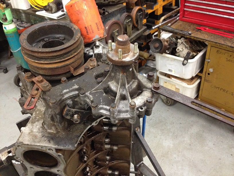
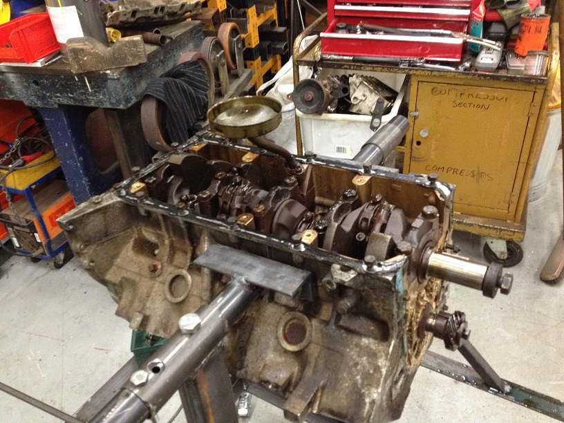
Any-how, time to see what lurks under the heads….
Now, if you are removing the engine normally it all stays on and lifted out as a lump as the heads have the lifting points, but I suggested will pull the heads so Adam could see inside and also as the body is off, slinging the engine without the heads isn’t too difficult as you can get the slings under the engine easy enough with no body panels in the way.
Undo the bolts forking from the centre outwards in a spiral pattern (follow RAVE).
With a light tap from a rubber faced mallet, the heads lift off. Note, they are doweled so don’t be trying to launch them sideways, just a love tap to crack the seal, and lift upwards.
Looking a bit nasty and corroded in there…no wonder it is seized solid….
The Right Hand Head had two valves stuck open, so looks like new valves, stems and seal as a minimum…
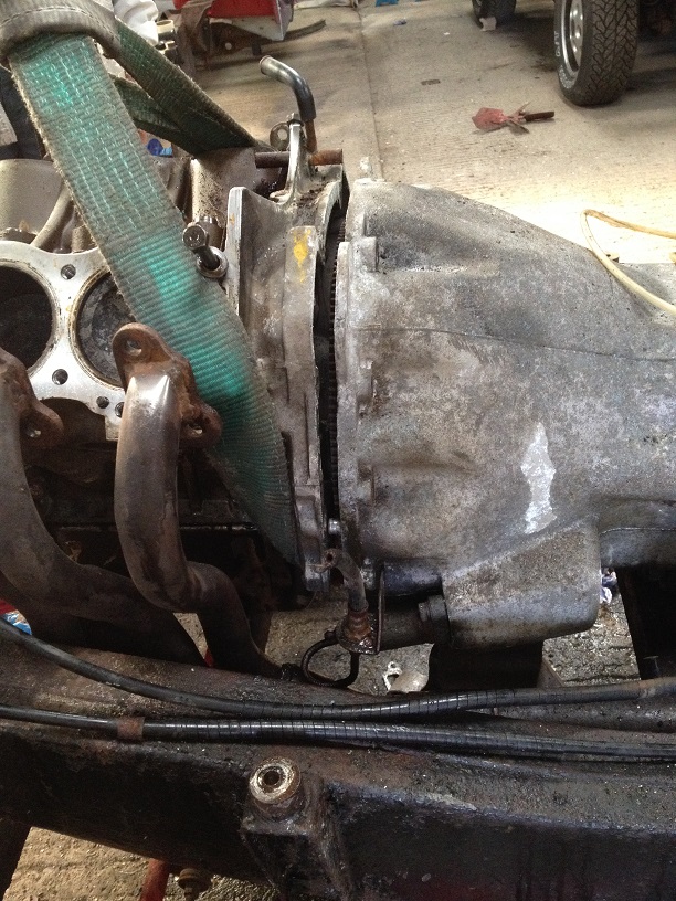
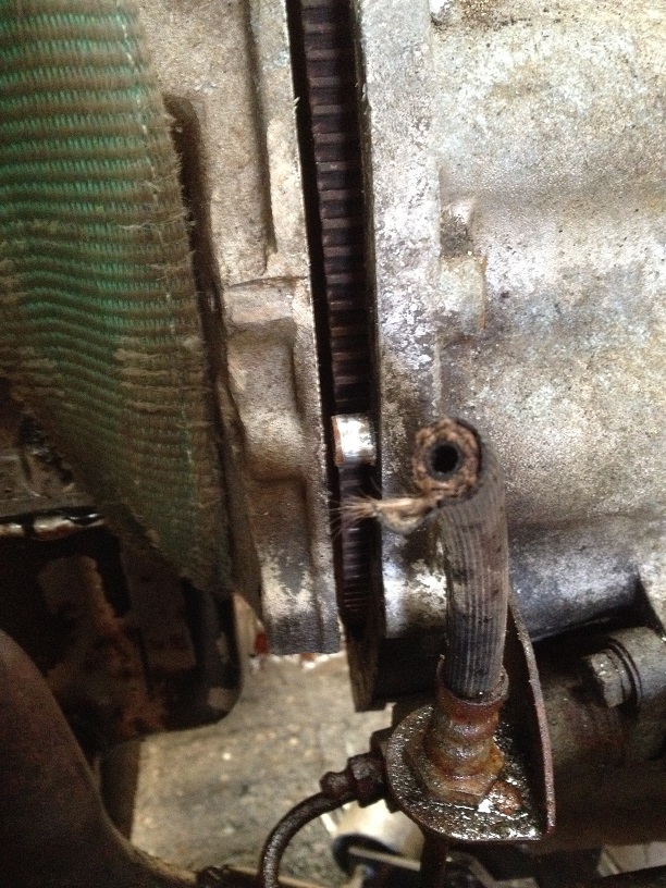
Time to free the engine….
Climb underneath and remove the fly wheel/bell housing cover plate
Using a jack and block of wood, support the gearbox
Remove the bell housing bolts, but leave the top two in for the moment.
Sling the engine carefully to avoid placing stress on any fragile components.
Take a bit of strain on the crane and start to undo the engine mounts from the block
Double check the rigging and strain on the straps and then remove the last two bellhousing bolts. Start to gently lift the engine a few mm, then pull the crane away slightly and pop the bellhousing from the engine. This is doweled too, so dn’t lift the engine to high or bash the bellhousing up or down.
With a jiggle, they will slide apart, slowly pull the engine forward to slide the gearbox input shaft from the clutch/flywheel.
Next is a bit tricky, you have to lift the front of the engine up at an angle to clear the front chassis cross member….easiest way is to use an adjustable lifting beam (about £40) but with a tremendous amount of luck, we had slung the engine almost perfectly to naturally sit at this nose high angle!
Gearbox input shaft spines, bearing and clutch fork looks in near perfect condition, even the grease on the components was still the golden grease colour!!
Drained the oil and strapped to a pallet.
Back at the workshop, as the crank is seized solid it makes it easy to undo the flywheel bolts, before removing the flywheel, mark its position to the crank.
The Clutch surface looks spotless and there is no ridge on the edge, so has been well driven and looked after previously!
Knocked up a temporary stand to seat her on and dropped the sump, glad that as this point I hadn’t put the block on the rotating stand I was building and turned I upside down, as the sludge in the bottom of the Sump Pan was errr…about and inch thick with emulsified oil, water, gunge, carbon etc….nice!
Left her on this temp stand since Sunday until Thursday with the bores filled with a 50/50 mix of Hypersolve (we aren’t allowed Acetone at work – to flammable – but we are allowed Acetylene and Oxygen gas….go figure) and Dexron III ATF…..
Best is Diesel, but that’ll stink out the workshop and the boss won’t be too happy with me….so this is the next best thing……
Acetone or other solvent cleaner will start to attack the deposits that are sticking the pistons to the liners, and the ATF is a great lubricate, detergent and penetrant…able to soak in and even run up through capillary action….good stuff.
Rotating stand almost finished
I am not a fan on the rear mounting stands…..too much leverage action on the bellhousing for my liking, so this bolts to the side mounts which are designed to support the engine weight in the first place!
Making the lift from one to the other….
Now able to rotate and station the engine top side up, upside down and on its end, the task of stripping the block can start.
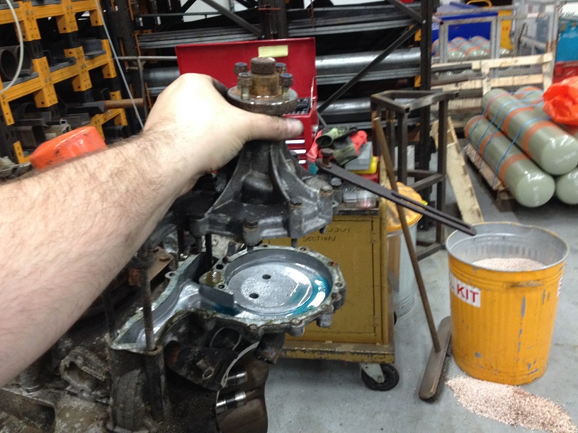
Again as the crank is solid, removing the crank bolt was simple enough….I will be looking to make a holding tool for the refit!
Noticed this little sticker on the side of the timing cover….
Which indicates the correct Cam for the 8.13:1 Compression Ratio engine, which this one is!
First off, remove the dizzy…..mark its position for referenceand undo the clamp to withdraw (with a tug) from the timing cover….DO NOT pull on the rotor as you can dislodge the bobweights in the advance mechanism.
Unbolt the water pump – Note some bolts are longer than others and also are different head sizes (as these ones also go into the block!)
Very clean underneath the pump, as the corrosion inhibitors in the fresh coolant have done their job (another reason to keep yer cooling system fresh!)
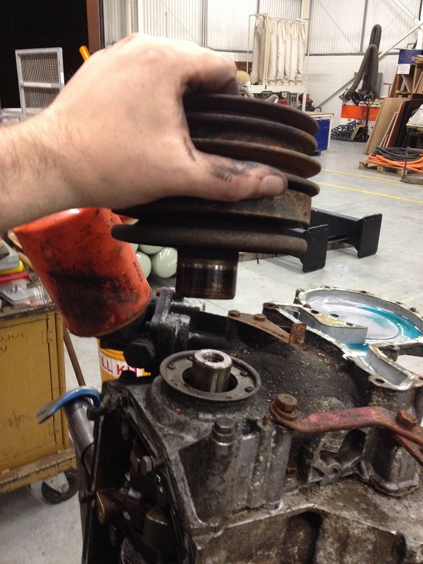
Remove the crank pulley and damper assembly….this can be tight on the shaft so a puller is required, this one was just a little wiggle and off she came!
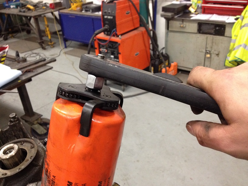
Remove the old oil filter, tried the chain wrench, but this filter was done up tight! So out came the more persuasive tool…..
Next is to remove the oil pump drive housing as one of the cover bolts sits under this. All but one bolt came off, this little fecker was rusted and rounded off, so unfortunately I had to cut this one off and then I will get the stud out later.
Mark the oil pump gears in relation to each other (as over time the teeth wear to match their meshed opposite and work more efficiently) and carefully withdraw from the housing….stuff rag into the housing for protection of the machined faces of the pump.
So undo all the remaining timing cover bolts and remove the cover. Underneath the cover shows some more lovely corrosion. Mainly aluminium oxide dust, will see how well it cleans up.
Again, as the crank is locked up, removing the camshaft bolt was simple enough….
Pull the hydraulic lifters out and keep in cylinder order. Submerge them in fresh engine oil (these ones will be soaked and pumped up prior to refit as they show very little wear, as does the camshaft)
Withdraw the dipstick tube….
Flip the engine over and remove Oil Pick Up…..
Now the fun can begin!!
Time to remove the con rod caps in a bid to free the crankshaft. As can be seen some of the cap bolts are buried down close to the side of the block with no space for a spanner or ratchet….a deep angled ring spanner might have reached, but I don’t have any of those (now on order btw!!) so I made a substitute from a 1/2” bi-hex socket welded to a bit of box section with the back cut off to fit down next to the block….
Remove the crank bearing caps and keep in order. The rear cap has a seal down the sides and sealant at the base, so can be a tight little fart to get out.
Crank journals look in great condition too, as are the bearing shells from both the crank and con rods!!
Hoping I could then lift the crank out were thwarted by the fact the Gudgeon pins in the pistons are seized solid and the con rods wouldn’t move to the side as the crank was lifted….
I had to get pistons to move to get the crank out….
So, a couple of crank caps back on, and flipped the engine over.
Machined up an aluminium drift to sit on the piston crown, and using a reaction riveting gun, applied vibration to the piston to try and crack any deposits holding the piston in place. Then flipped the engine back over, and using a drift started knocking the piston down the bore. Unfortunately the only place available to drift from was the ends of the con rods, and in some cases of the really stubborn pistons, there is small burring on the end of the rod, hopefully we’ll be able to clean these up later.
With them move down sufficiently the crank can be lifted out!
Using the vibrate method, I move each piston to the bottom of the bore, cleaned out the crap from above the piston on the bores, then using a block of wood, drifted the pistons back out again….
Mark each piston assembly with its location once removed.
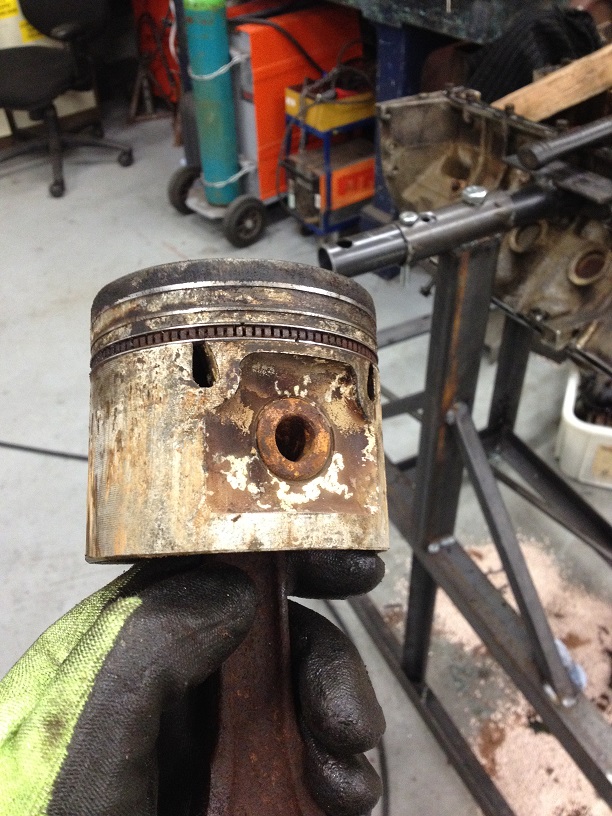
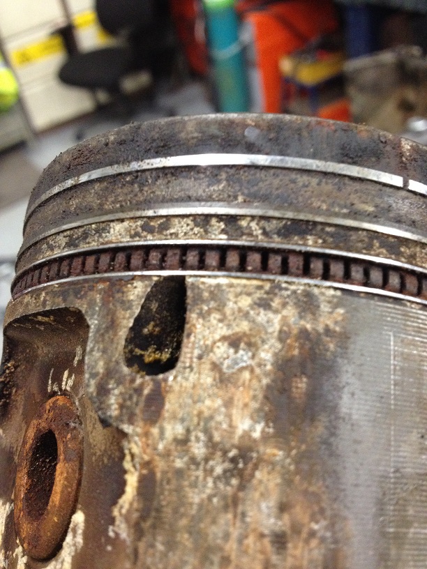
Pistons are dirty and corroded, the gudgeon pins are seized solid, so I will soak them all in a 50/50 mix of solvent and ATF again for a few days and see if I can get the pins to move!
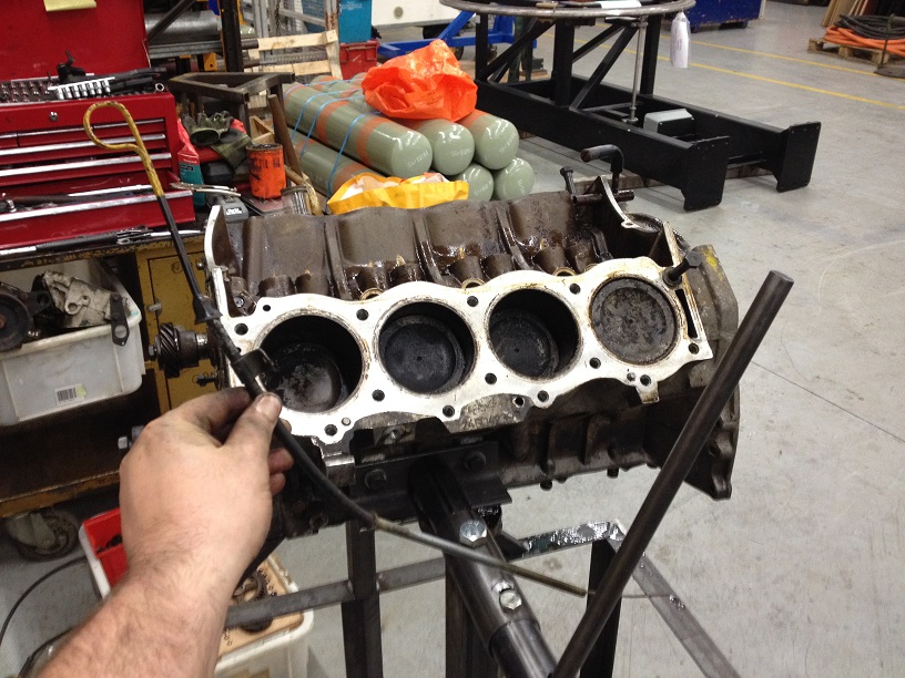
Block with the pistons out….bores look a little messy, but after a brief clean I think it just requires elbow grease, paitience and once the heavy deposits are out, the stubborn ones will move with the honing stones!
Carefully withdraw the camshaft (this can be done once the timing chains are off, but for an un-known reason I left it in the block…..excitement to get the pistons out I think…..if you have left it in, as you rotate the engine, you have to be mindfull not to let the engine go nose down else the cam will slide out!
Cast on the side of the cam is a number. Not sure this is a part number or casting number as no details are listed under this reference HRC1619 so I can only assume it is the number of the cast used to forge the cam!
So, now we have a bare block and a couple of boxes of bits!
First thing to do is clean the bores, if they can be cleaned up without needed to bore them out, happy days, then everything can proceed…..there is little point in doing anything else until we can see if the block can be saved first…..that’s the next instalment!
Last edited:
")