- Posts
- 16,482
So, following on from my previous thread about timing the 300Tdi FIP (found here: https://www.landyzone.co.uk/land-rover/it-should-be-simple-300tdi-fip-timing.311147/ )
I took the day off today to change the timing belt, crank sprocket, idler and tensioner. It would also give me a chance to reset the FIP timing.
As could be seen from the previous thread, when I did a recon view inside the timing cover, the crank sprocket was slowly munching the woodruff keys (typical when muppets don't torque the crank bolt up properly!) so that all needed to be addressed to.
So with no more gilding the lilly and further ado, lets get to it!
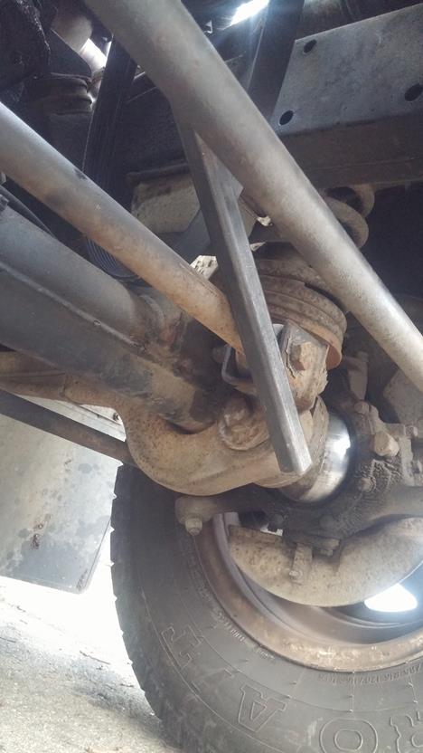
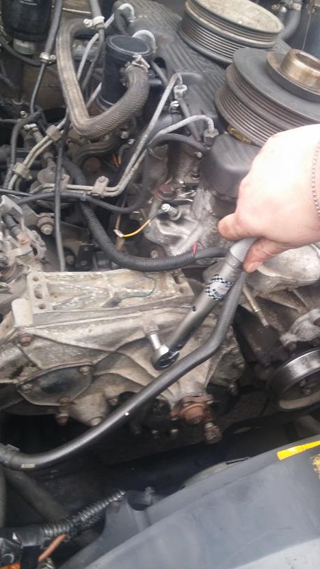
First is to remove the viscous fan unit (mine doesn't have one - but if yours does, you'll have to remove it! - remeber it is a lefthand thread)
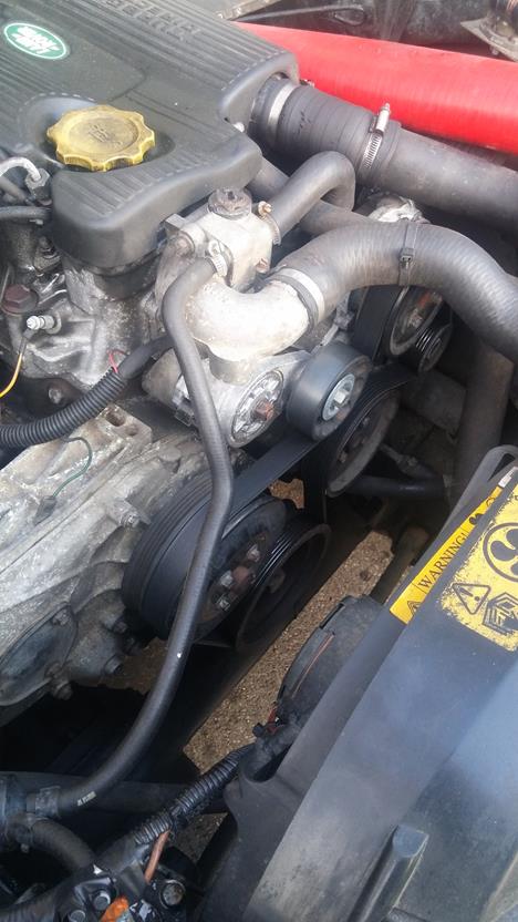
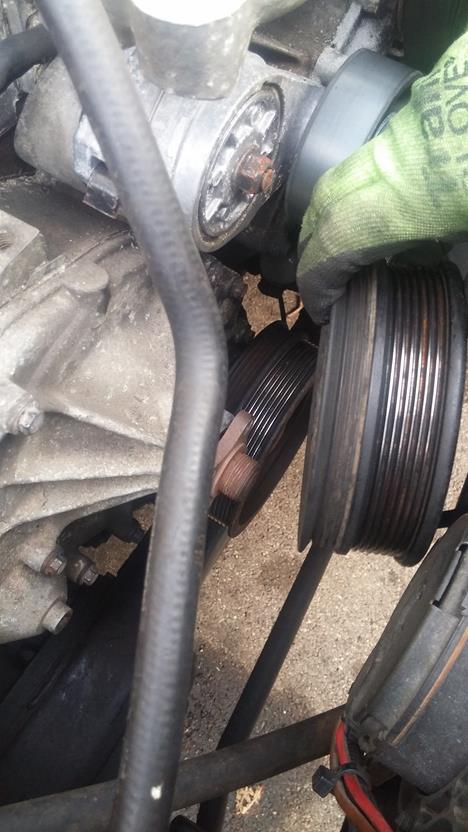
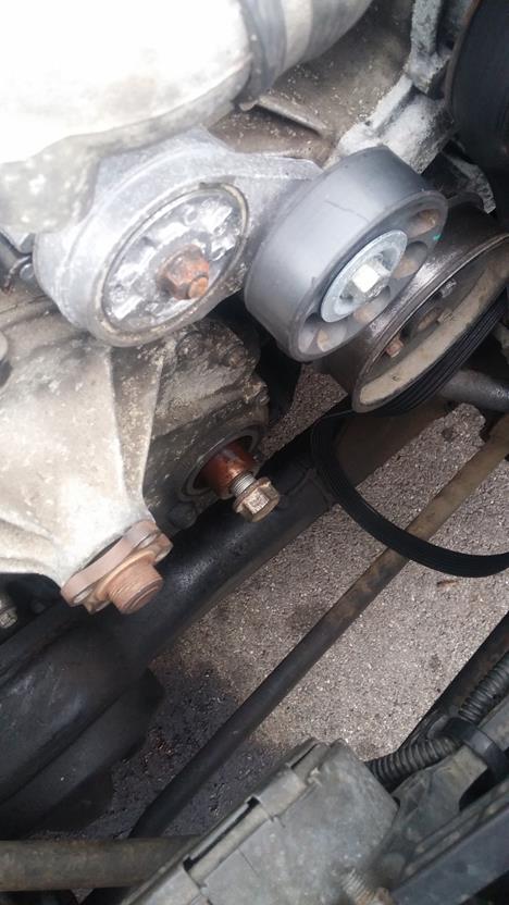
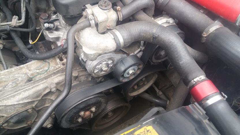
While the drive belt is on, loosen the idler pulley nuts using a 10mm socket
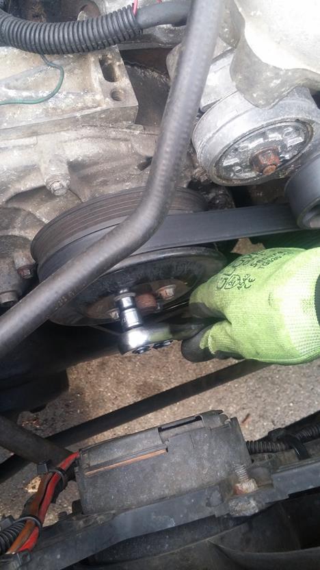
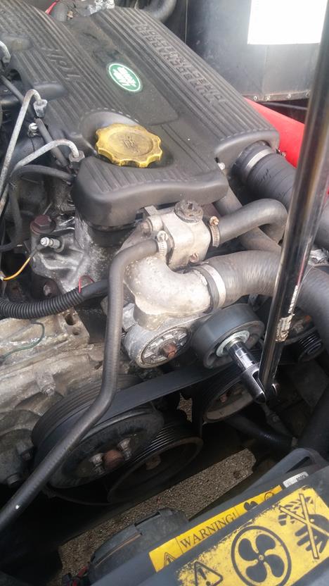
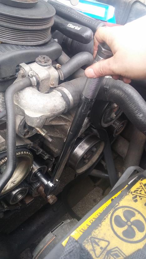
Using a 15mm socket or spanner, rotate the belt tensioner up and away so the belt can be removed from the pulleys
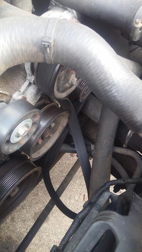
Continue to remove the ldler pulley
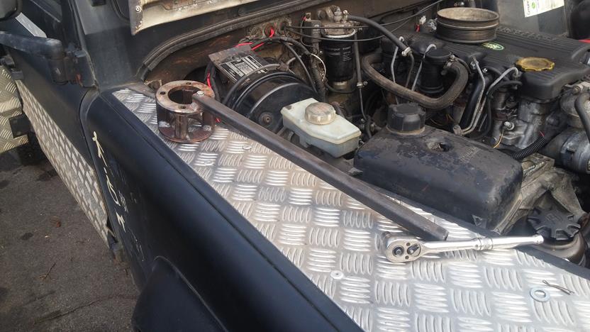
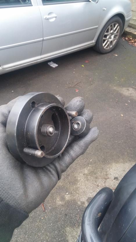
When I did our 200Tdi powered Ninety Truck Cab ( How to here: https://www.landyzone.co.uk/land-ro...ange-and-cylinder-head-refresh-how-to.282586/ ), I made a pulley holding tool - the 200Tdi has a deep dish to the crank pulley hence why it is so tall, for the 300Tdi, it is a little too tall but it does the job. I'll post the dimensions for this tool at the end (when I find them!)
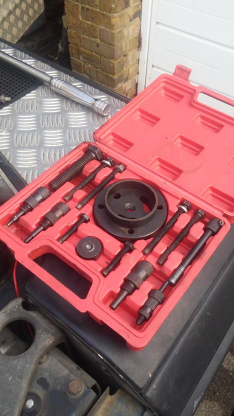
Using the longer bolts from the Timing Kit - relatively in-expensive from the bay of E
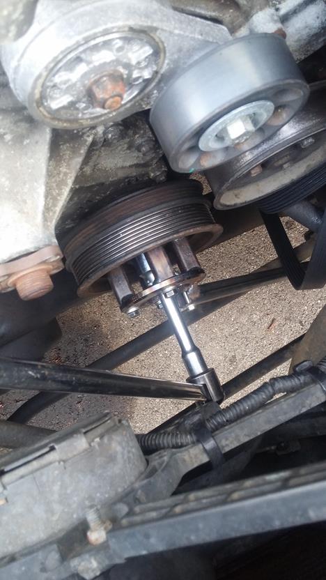
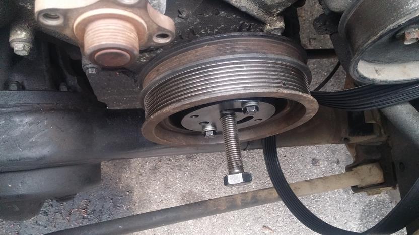
Bolt the pulley holder to the pulley and brace against a good hard point
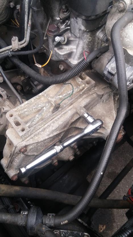
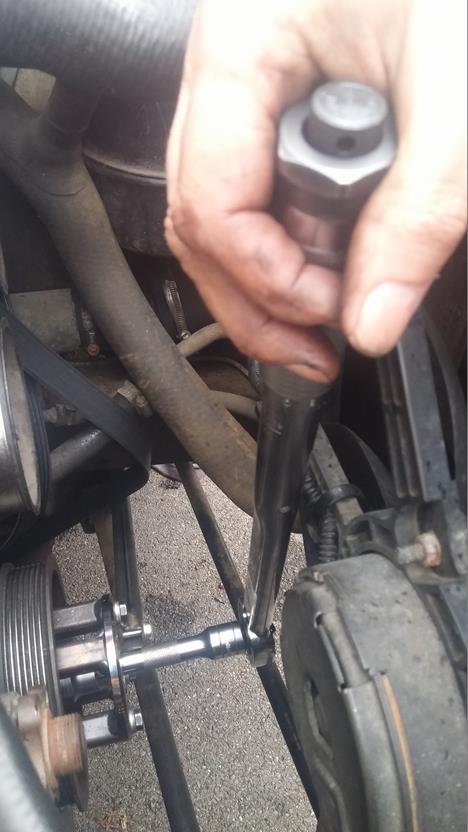
Using a long breaker bar and plenty of effort (if the last person did it up properly that is!) undo the crank bolt with a 27mm socket.
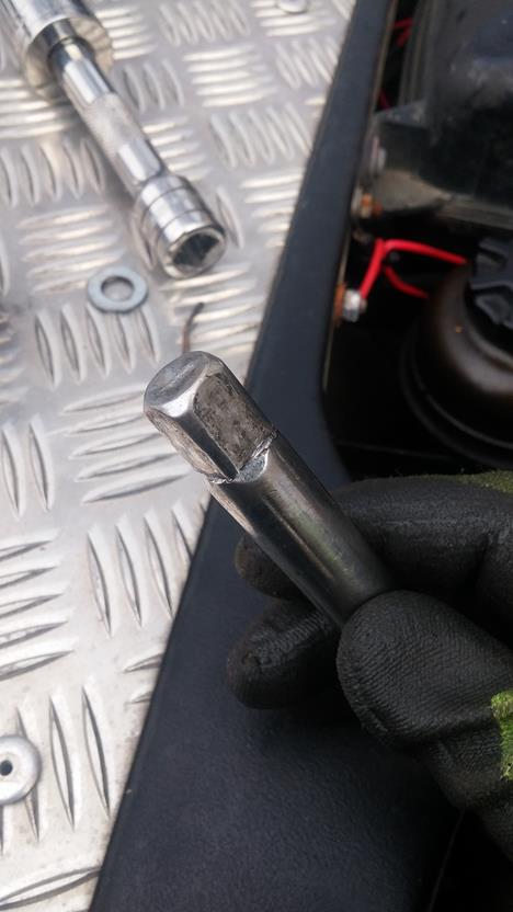
After my recon I re-did the bolt up to FT - on undoing it today, I managed to shear the short 3/4" extension bar!!
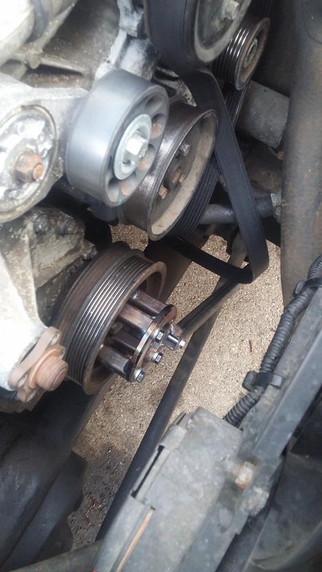
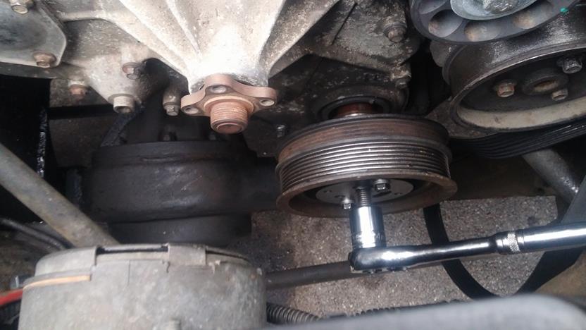
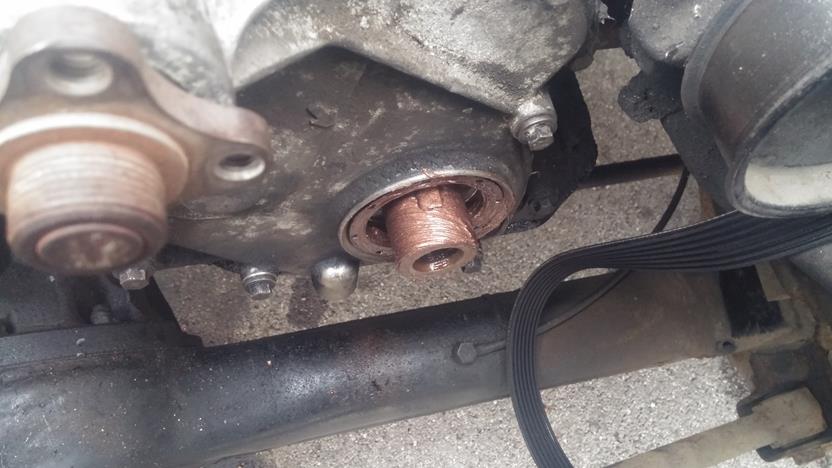
Once you have regained your breath and feeling in your shoulders, time to pull the crank pulley off. Using the puller in the timing kit with the centre plug fitted into the end of the crank.
Now, the pulley can be sodding tight to remove as they tend to rust to the shaft, so be prepared for a fight again!
Once finally removed, take a break and grab a coffee, the hard work is done for now!
Put the crank bolt back in the crank so you can turn the crank as required.
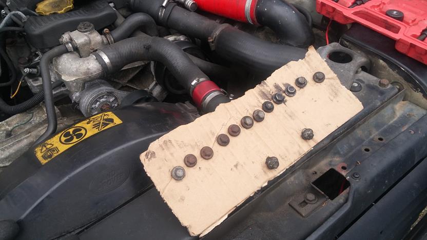
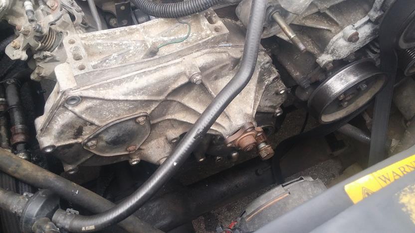
Time to remove the timing case front cover, simply undo the 14 bolts with a 10mm socket.
Using a piece of card or similar, note where the bolts go, or the order in which you took them off.
Using a small pry or blunt screwdriver, gently ease the cover off. It is located on dowels so don't hit it about. it is only cast aluminium and could crack!
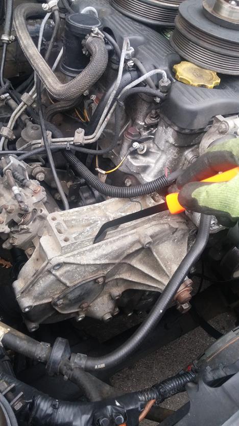
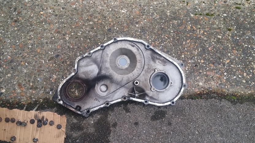
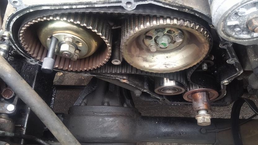
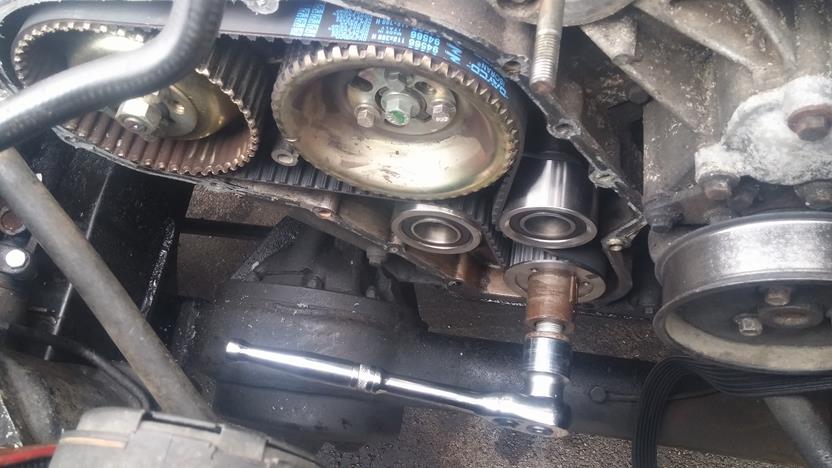
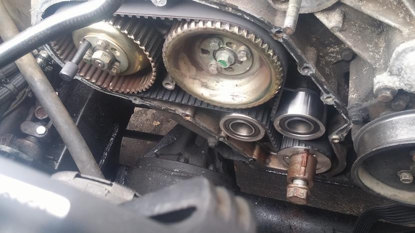
You can now see the wonders of the timing belt!
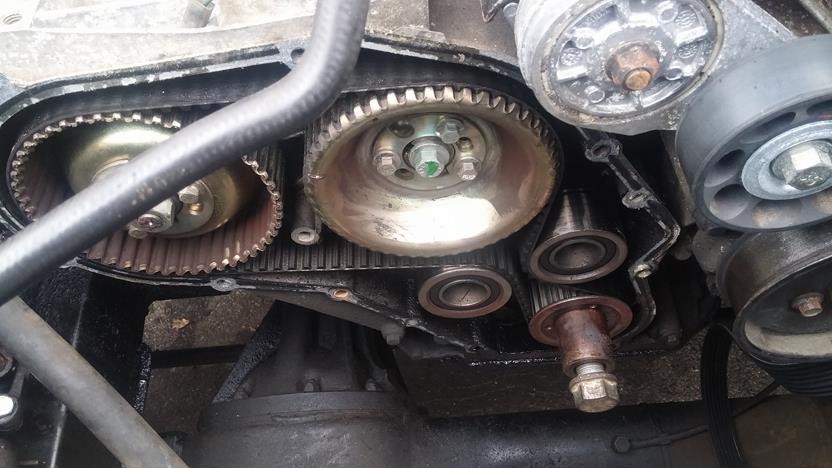
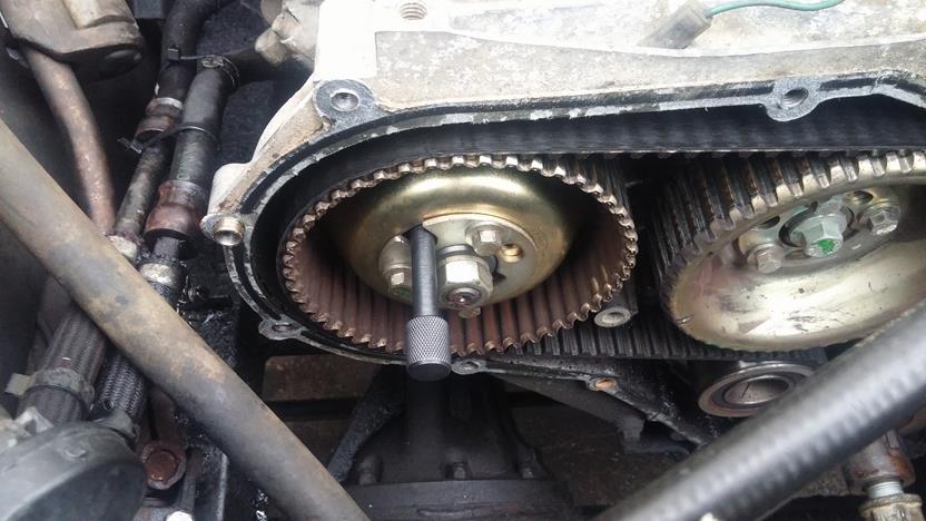
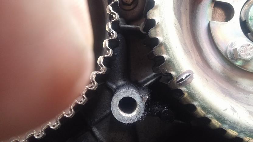
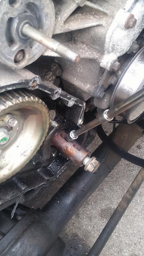
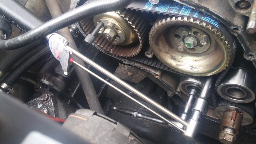
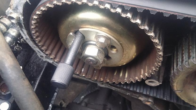
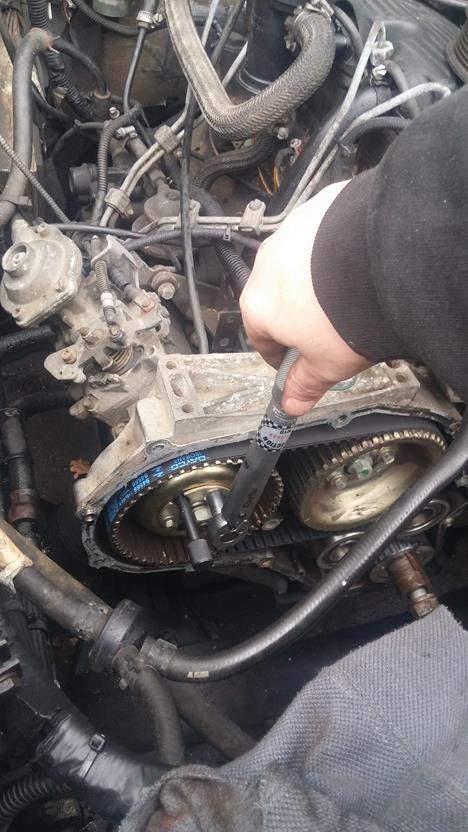
Using the crank bolt, rotate the engine to TDC (remember to crank turns twice for each rotation of the cam and FIP) so keep turning until the woodruff keys are uppermost, the Cam timing mark is aligned with the peg and you can place the timing pin in the FIP - or a 9.5mm drill) - Sorry about the thumb in the Cam photo below! Fit the Flywheel locking pin.
Once the FIP is locked in place, loosen the 3 FIP pulley bolts using a 10mm socket to allow the belt to move.
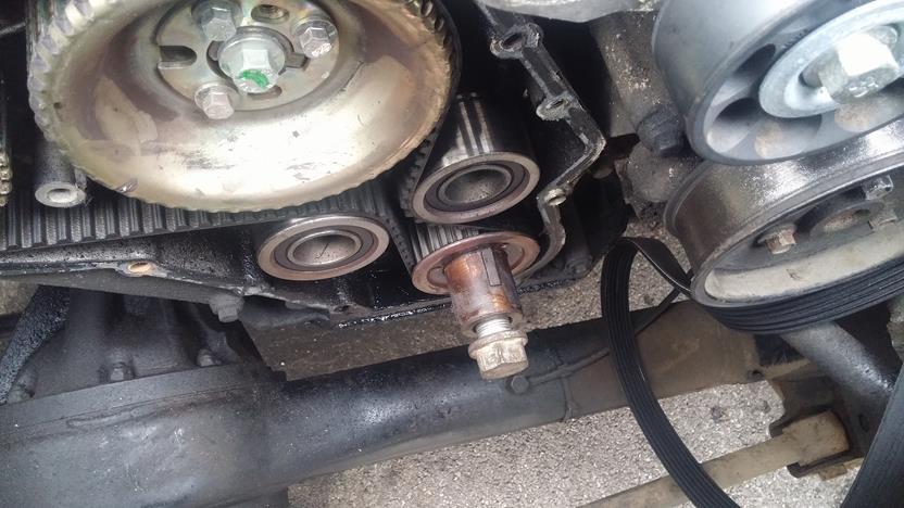
Remove the tensioner holding bolt with an 8mm allen key or allen socket. The tensioner and idler are both located on the same backing plate.
Next, remove the idler nut using a 15mm socket
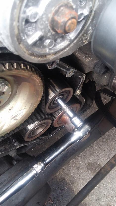
And remove the idler
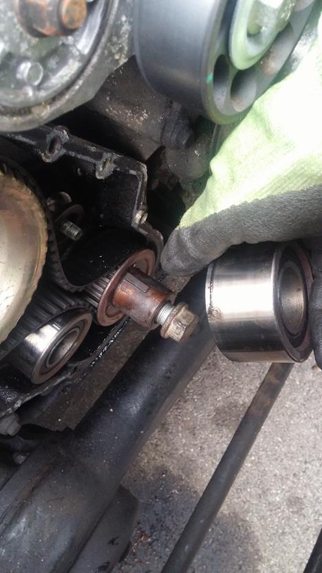
Slide the belt off the pulleys and sprocket along with the tensioner pulley
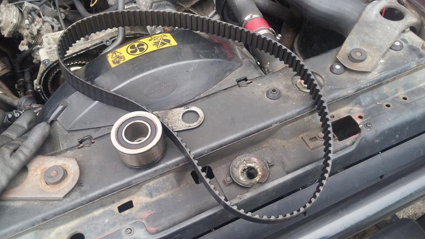
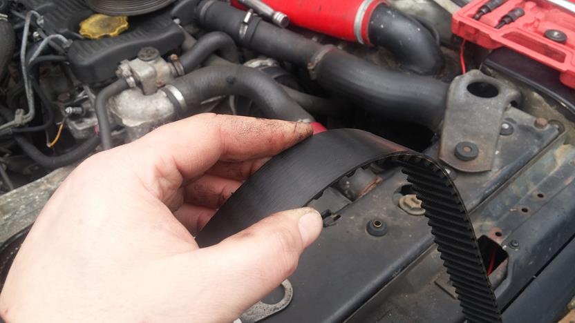
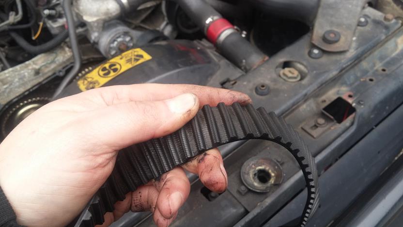
On closer inspection, the belt (along with the idler and tensioner pulleys) looked in good nick and can't have been done too long ago - pity the tw*t who did it didn't do the crank bolt up properly!
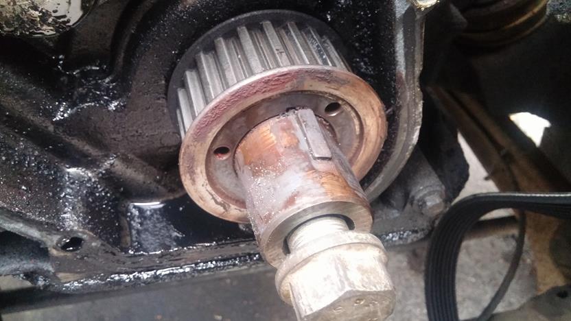
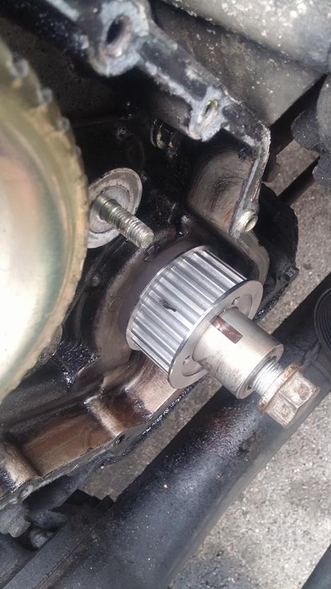
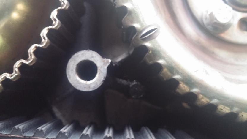
The offending crank sprocket, it can be seen the keyway and woodruff keys don't line up!
Quick check of the Cam timing mark again - for peace of mind!
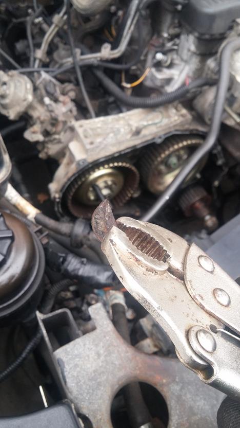
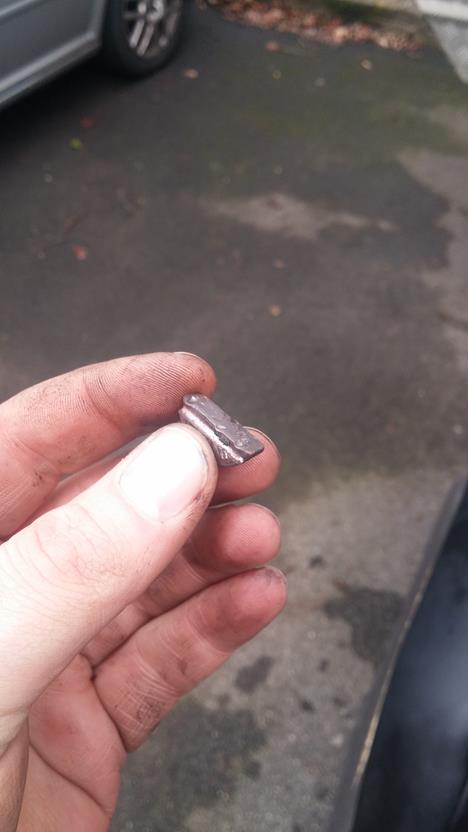
With a wide, flat drift knock one end of the woodruff downwards so it rotates in its keyway upwards and can then be gripped and removed.
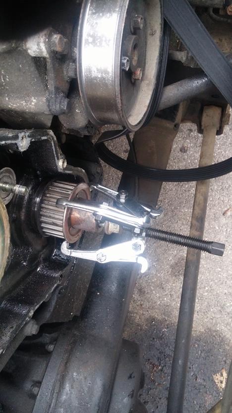
Using a puller - this one is not ideal if you plan to reuse the sprocket as it could damage the side flanges - remove the sprocket. Previously on the 200Tdi, I used the Crank Pulley puller from the kit along with some M5 stud screwed into the sprocket and pulled it off that way - link to that How To is above!
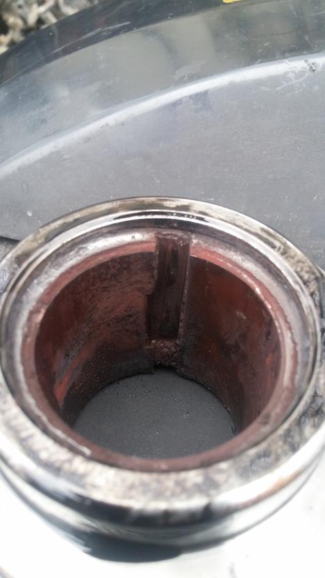
Once removed you can see the damage caused by the sprocket chattering away and wearing out the internal keyway
So, time to remove the damaged woodruff key. Using the same method as above, drift it down on one side so it rotates up and out from the keyway slot. I had to remove the drive belt tensioner to be able to get a good whack on the hammer to drift the key out - I used a sacrificial 6mm allen socket on the end of a couple of extensions as space was limited!
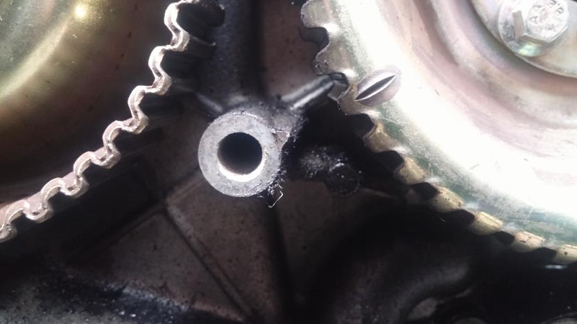
You can now see the damage to the keys done by the sprocket chattering away
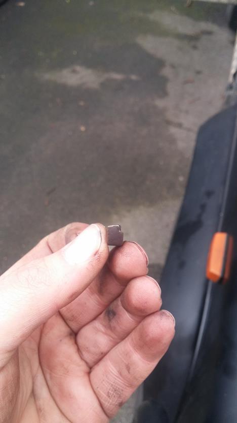
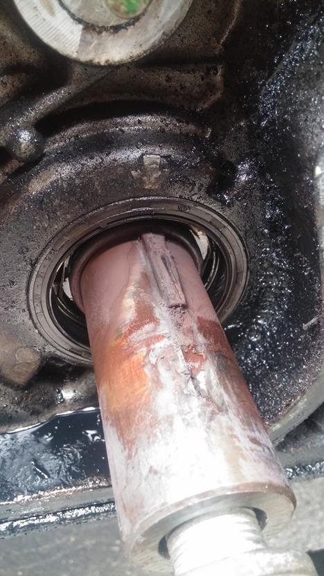
Thankfully the crank keyways were undamaged - phew
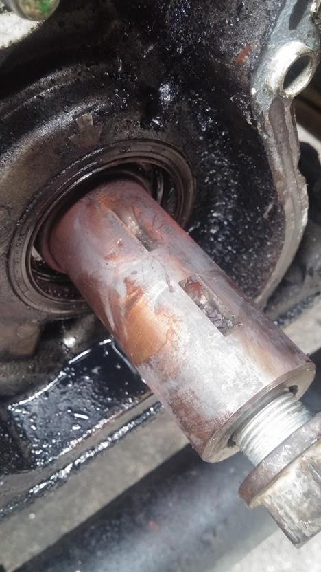
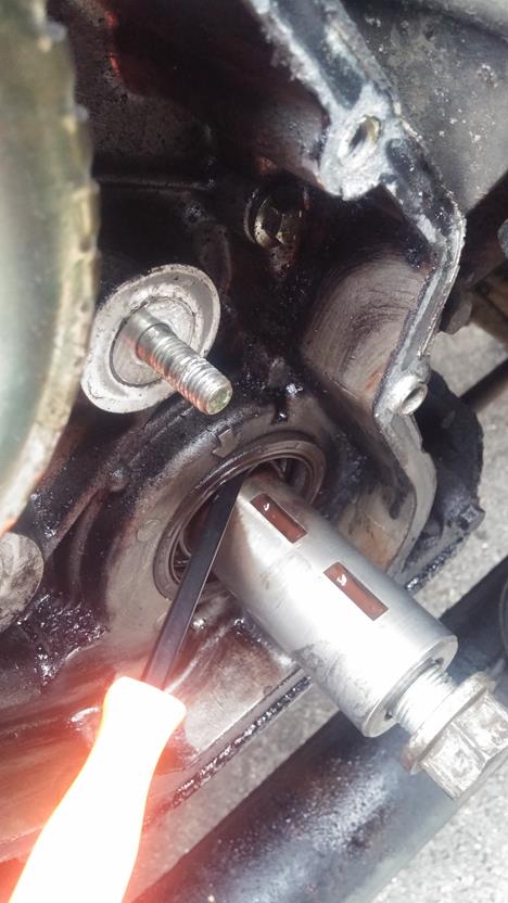
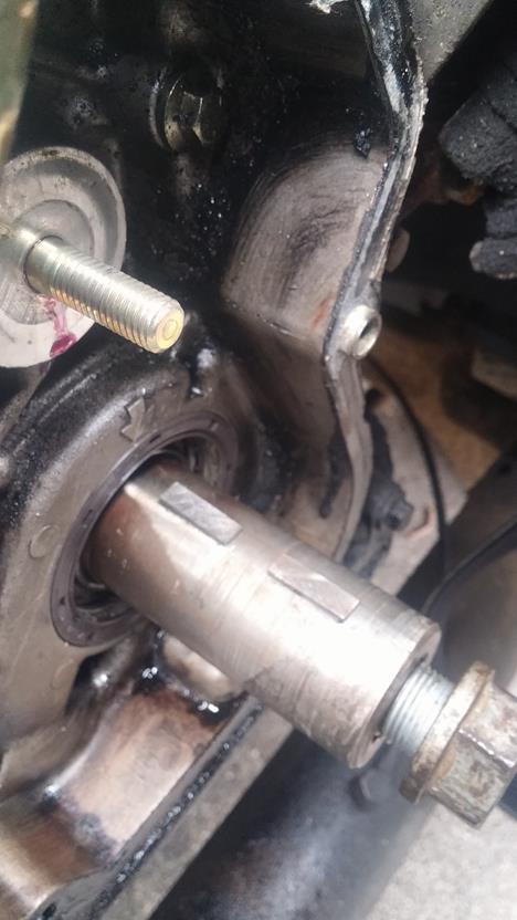
Time to clean up the crank. Using some emery paper and a squirt of oil, rub down the crank to remove the rust and deposits.
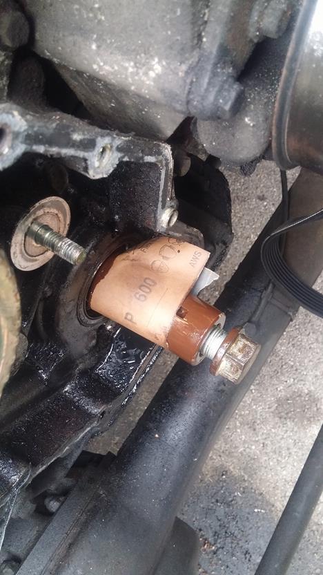
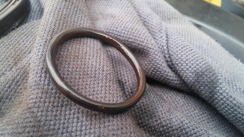
Using a seal removing tool or similar, remove the inner crank seal and O ring.
Again, looking at the condition of the seal and the O ring, they don't look to old - so why go to the effort of doing the seal, belt etc...but don't do the crank bolt up properly - muppets!
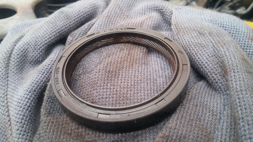
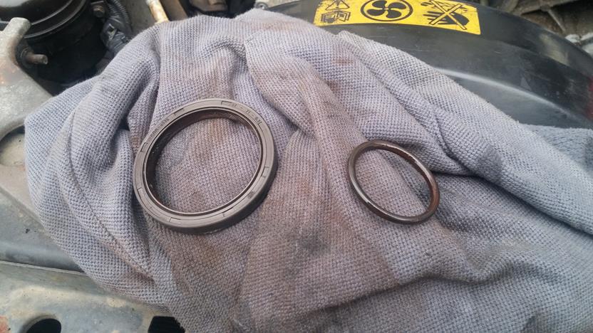
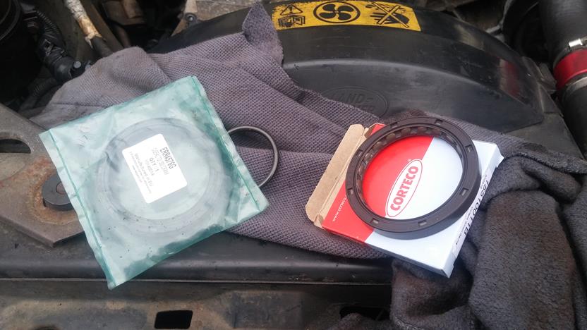
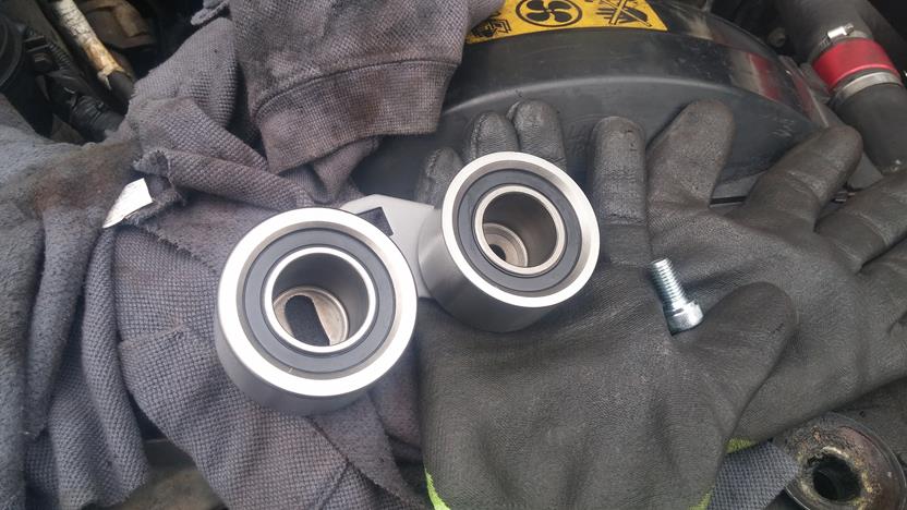
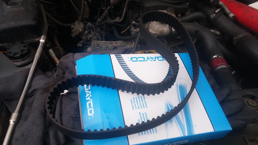
Get your new seals ready for the refitment
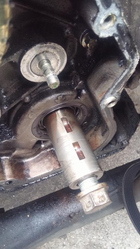
Place the new seal into the recess, and I use the new sprocket as a slide hammer to knock the seal home squarely. Once fitted, fit the new O ring in place too.
Turning our attention now to the Idler/Tensioner refitment, using a double nut method and lock together, remove the stud for the idler pulley.
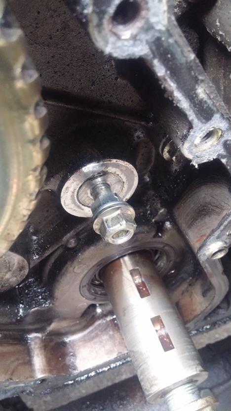
With some thread locking compound (Loctite or similar) apply to the shorter end of the idler stud
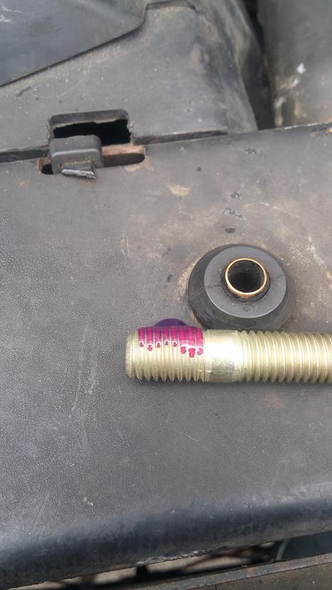
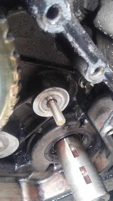
Using the double nut method locked together again, screw in the idler stud and tighten to 10N.m (thanks Neilly)
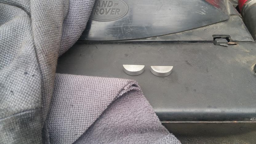
Time to fit those shiny new woodruff keys - they are a tight fit, so I use some fine emery paper and just gently rub them on one side so they just fit, then knock them home with a large flat drift.
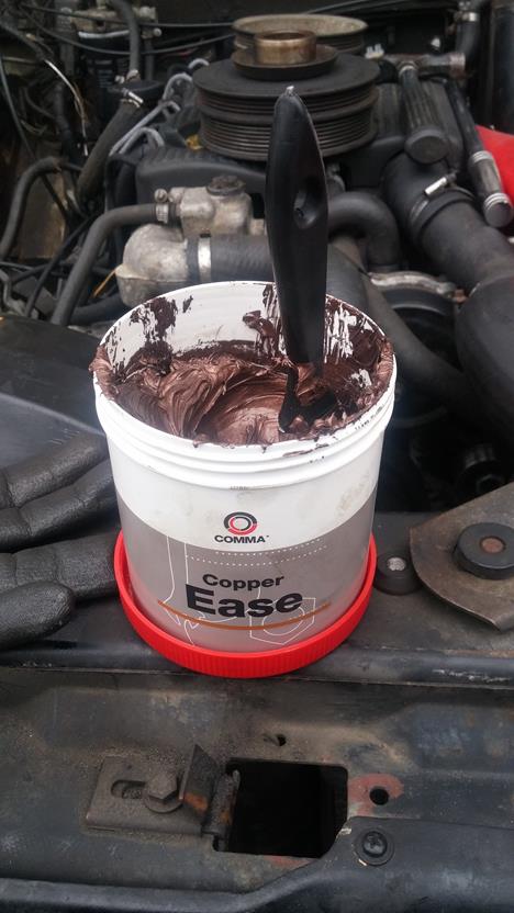
To ease removal in the future, apply some Copper grease to the crank shaft and slide the new sprocket fully home.
Time to fit the idler and tensioner assembly.
The Idler fits into the backing plate and is placed over the new stud. Torque the idler nut to 45N.m, also loosley fit the new tensioner socket cap bolt into place.
Time to now fit the new timing belt. This can be a fiddle, but take your time and be careful not to move the Cam pulley - keep checking it is still aligned with the timing marks.
Make sure the FIP pulley is rotated fully clockwise, and slip the new belt over the crank sprocket, whilst keeping tension on the belt slip it under the idler, over the Cam Pulley and over the FIP pulley. Now, twist the belt along the long length between the FIP pulley and the tensioner to allow it to slip over the tensioner pulley.
Once the belt is located, ensure there is no slack on the righthand side of the belt - the part between the sprocket, idler and Cam pulley. All the slack should be on the FIP to Tensioner section of the run.
Now, this is the critical part and must be done to the letter to prevent premature wear and to ensure the timing is correct.
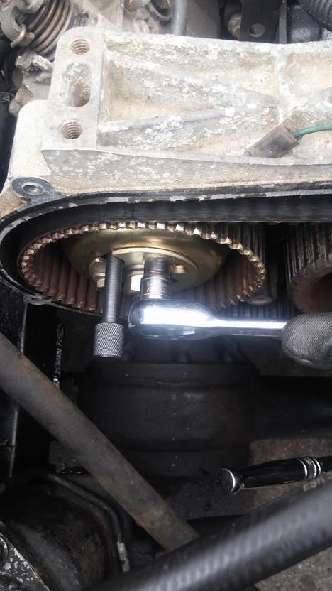
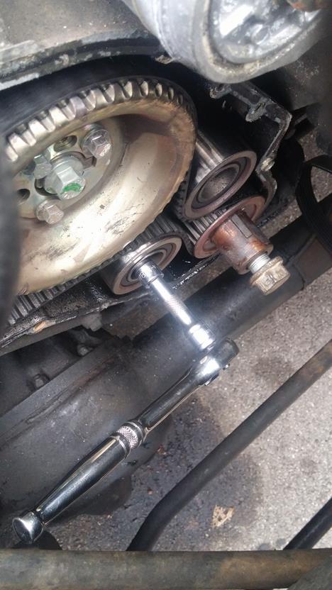
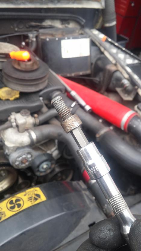
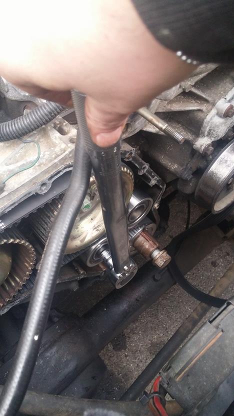
Using a torsion bar style torque wrench and an extension bar that fits the square drive socket of the tensioner backplate, apply tension to the belt until the torque reading is 11N.m, at this, tighten the tensioner bolt up to hold it in place.
Tighten the FIP pulley bolts up, and remove the locking pin. Remove the flywheel pin and using the crank bolt, rotate the engine clockwise, twice.....remember the crank turns twice for each single rotation of the Cam and FIP.
Once back to the start (TDC of No1 cylinder) put the flywheel lock pin back in, and check to ensure the FIP locking pin slips back in to lock the FIP in place, and also that the Cam timing marks are back where they should be too.
Now, loosen the FIP pulley bolts again and also the tensioner locking allen bolt. Repeat the belt tensioning process again, using the torsion bar torque wrench to 11N.m and tighten the allen bolt to 45N.m
Now tighten the FIP pulley bolts to 25N.m
Once done, remove the locking pin and the flywheel locking pin. Rotate the engine crank twice again and back to TDC, recheck the timing marks and FIP once again....if it all still lines up - jobs good, if not. Lock the flywheel, FIP and start again.
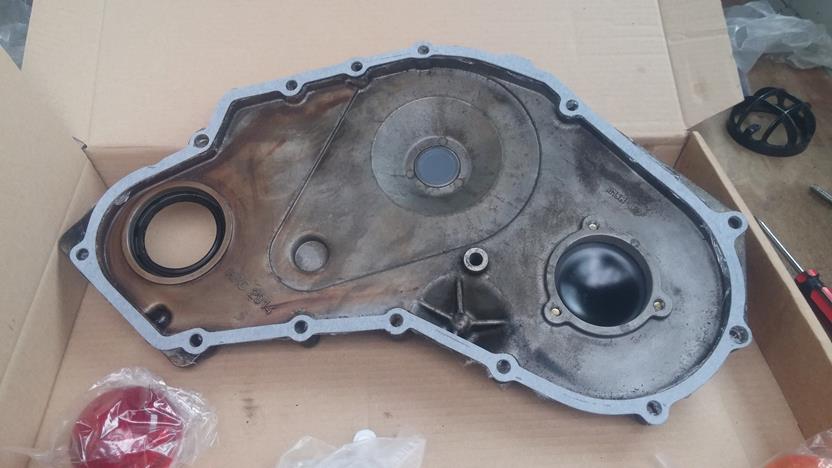
Once you are satisfied it all lines up, it is time to prepare the timing case front cover for refitment.
Knock out the old cover seal being careful not to damage the front cover or the recess the seal fits into
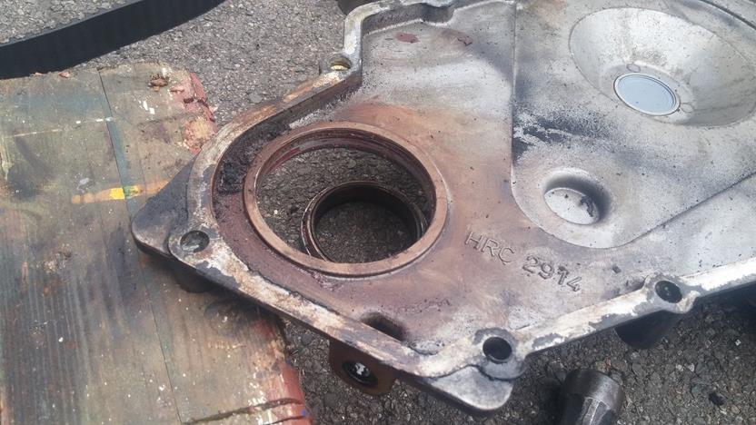
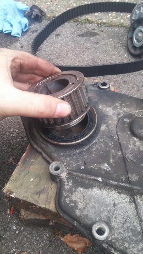
Clean the cover and the recess the new seal will fit into. Place the new seal in place and drift into position - I like to use the old sprocket for this as it gets it in nice and square and seats it in the right place!
Clean the mating faces of the timing case and the front cover. I use a smear of red Holymer to hold the new gasket in place while refitting the front cover as it stops it from moving about!
Fit the timing cover over the dowels and into place
Refit the 14 bolts in the right place and torque to 25N.m
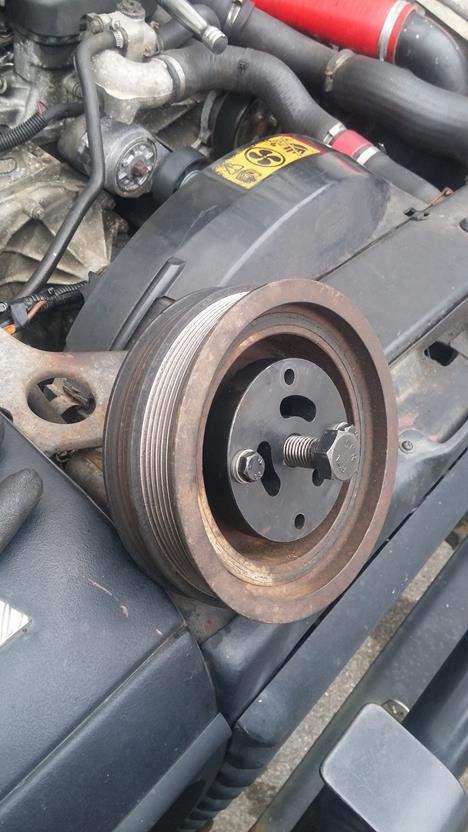
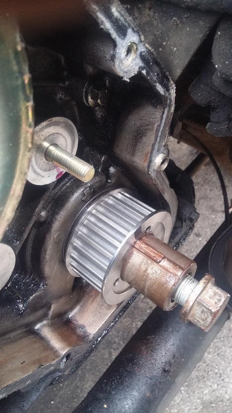
Apply a smidge more copper grease to the crank and slip the crank pulley back in place.
Now this part is also critical - because if it is skipped or skimped it leads to the problem I have just resolved!!
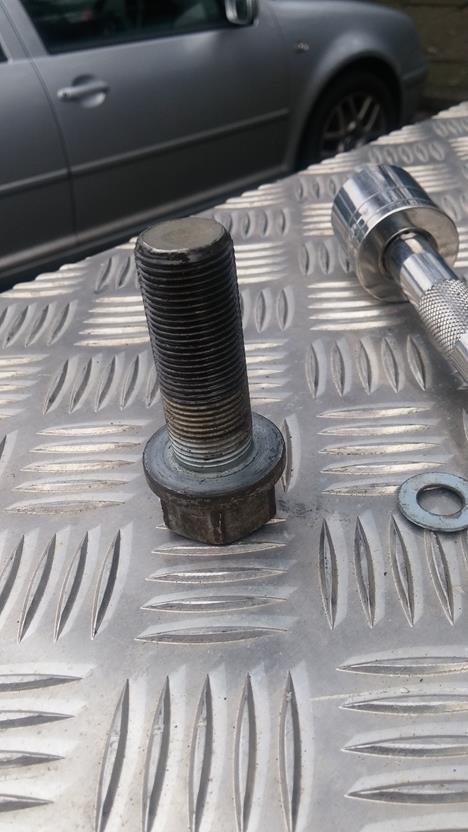
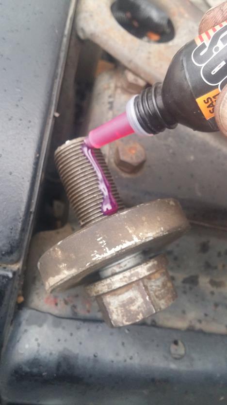
I opted to refit the original bolt as there was nothing amiss with it, but new bolts *may* come with some locking compound already applied. Apply some locking compound to the threads and screw into place.
Refit the pulley holding tool in a similar manner to previously, this time ensuring the tool will be held in place while doing up the crank bolt.
Do the initial torque up to 80N.m
Now you really need to start huffing and puffing - I am a big lad and this part gets me pumped and afterwards I need 5 minutes to catch my breath.....yes getting the next 90deg turn of the bolt is HARD WORK but MUST be done.
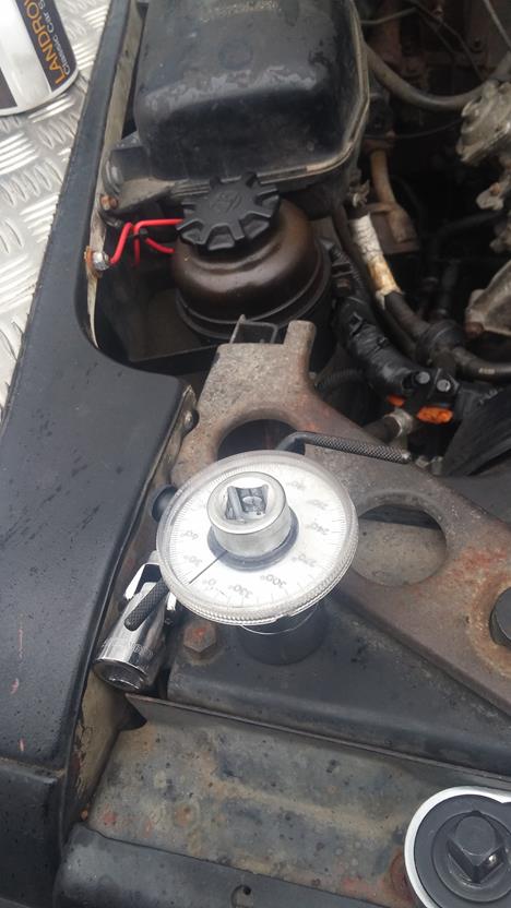
Turn the crank bolt a further 90deg turn, measure using an angle gauge.
Once you have recovered from that, refit the drive belt, and make a coffee.....
Now keeping your fingers crossed, she'll fire up and run sweet - mine did, and the plumes of smoke have gone - on cold start she did puff a little bit of white and blue, maybe my plugs are getting old and tired, but after 10 seconds she ran clear.
So, the run to work tomorrow will be a better test, as the 20 minutes of driving I did today to get a new side light bulb and a full tank fo diesel, didn't give it a full run, will report back tomorrow on the results.
Simples really.........So why do people not do the Crank Bolt up properly - its not fecking rocket science!!
I took the day off today to change the timing belt, crank sprocket, idler and tensioner. It would also give me a chance to reset the FIP timing.
As could be seen from the previous thread, when I did a recon view inside the timing cover, the crank sprocket was slowly munching the woodruff keys (typical when muppets don't torque the crank bolt up properly!) so that all needed to be addressed to.
So with no more gilding the lilly and further ado, lets get to it!
First is to remove the viscous fan unit (mine doesn't have one - but if yours does, you'll have to remove it! - remeber it is a lefthand thread)
While the drive belt is on, loosen the idler pulley nuts using a 10mm socket
Using a 15mm socket or spanner, rotate the belt tensioner up and away so the belt can be removed from the pulleys
Continue to remove the ldler pulley
When I did our 200Tdi powered Ninety Truck Cab ( How to here: https://www.landyzone.co.uk/land-ro...ange-and-cylinder-head-refresh-how-to.282586/ ), I made a pulley holding tool - the 200Tdi has a deep dish to the crank pulley hence why it is so tall, for the 300Tdi, it is a little too tall but it does the job. I'll post the dimensions for this tool at the end (when I find them!)
Using the longer bolts from the Timing Kit - relatively in-expensive from the bay of E
Bolt the pulley holder to the pulley and brace against a good hard point
Using a long breaker bar and plenty of effort (if the last person did it up properly that is!) undo the crank bolt with a 27mm socket.
After my recon I re-did the bolt up to FT - on undoing it today, I managed to shear the short 3/4" extension bar!!
Once you have regained your breath and feeling in your shoulders, time to pull the crank pulley off. Using the puller in the timing kit with the centre plug fitted into the end of the crank.
Now, the pulley can be sodding tight to remove as they tend to rust to the shaft, so be prepared for a fight again!
Once finally removed, take a break and grab a coffee, the hard work is done for now!
Put the crank bolt back in the crank so you can turn the crank as required.
Time to remove the timing case front cover, simply undo the 14 bolts with a 10mm socket.
Using a piece of card or similar, note where the bolts go, or the order in which you took them off.
Using a small pry or blunt screwdriver, gently ease the cover off. It is located on dowels so don't hit it about. it is only cast aluminium and could crack!
You can now see the wonders of the timing belt!
Using the crank bolt, rotate the engine to TDC (remember to crank turns twice for each rotation of the cam and FIP) so keep turning until the woodruff keys are uppermost, the Cam timing mark is aligned with the peg and you can place the timing pin in the FIP - or a 9.5mm drill) - Sorry about the thumb in the Cam photo below! Fit the Flywheel locking pin.
Once the FIP is locked in place, loosen the 3 FIP pulley bolts using a 10mm socket to allow the belt to move.
Remove the tensioner holding bolt with an 8mm allen key or allen socket. The tensioner and idler are both located on the same backing plate.
Next, remove the idler nut using a 15mm socket
And remove the idler
Slide the belt off the pulleys and sprocket along with the tensioner pulley
On closer inspection, the belt (along with the idler and tensioner pulleys) looked in good nick and can't have been done too long ago - pity the tw*t who did it didn't do the crank bolt up properly!
The offending crank sprocket, it can be seen the keyway and woodruff keys don't line up!
Quick check of the Cam timing mark again - for peace of mind!
With a wide, flat drift knock one end of the woodruff downwards so it rotates in its keyway upwards and can then be gripped and removed.
Using a puller - this one is not ideal if you plan to reuse the sprocket as it could damage the side flanges - remove the sprocket. Previously on the 200Tdi, I used the Crank Pulley puller from the kit along with some M5 stud screwed into the sprocket and pulled it off that way - link to that How To is above!
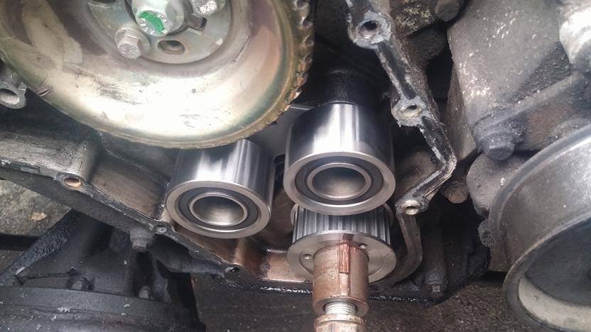
Once removed you can see the damage caused by the sprocket chattering away and wearing out the internal keyway
So, time to remove the damaged woodruff key. Using the same method as above, drift it down on one side so it rotates up and out from the keyway slot. I had to remove the drive belt tensioner to be able to get a good whack on the hammer to drift the key out - I used a sacrificial 6mm allen socket on the end of a couple of extensions as space was limited!
You can now see the damage to the keys done by the sprocket chattering away
Thankfully the crank keyways were undamaged - phew
Time to clean up the crank. Using some emery paper and a squirt of oil, rub down the crank to remove the rust and deposits.
Using a seal removing tool or similar, remove the inner crank seal and O ring.
Again, looking at the condition of the seal and the O ring, they don't look to old - so why go to the effort of doing the seal, belt etc...but don't do the crank bolt up properly - muppets!
Get your new seals ready for the refitment
Place the new seal into the recess, and I use the new sprocket as a slide hammer to knock the seal home squarely. Once fitted, fit the new O ring in place too.
Turning our attention now to the Idler/Tensioner refitment, using a double nut method and lock together, remove the stud for the idler pulley.
With some thread locking compound (Loctite or similar) apply to the shorter end of the idler stud
Using the double nut method locked together again, screw in the idler stud and tighten to 10N.m (thanks Neilly)
Time to fit those shiny new woodruff keys - they are a tight fit, so I use some fine emery paper and just gently rub them on one side so they just fit, then knock them home with a large flat drift.
To ease removal in the future, apply some Copper grease to the crank shaft and slide the new sprocket fully home.
Time to fit the idler and tensioner assembly.
The Idler fits into the backing plate and is placed over the new stud. Torque the idler nut to 45N.m, also loosley fit the new tensioner socket cap bolt into place.
Time to now fit the new timing belt. This can be a fiddle, but take your time and be careful not to move the Cam pulley - keep checking it is still aligned with the timing marks.
Make sure the FIP pulley is rotated fully clockwise, and slip the new belt over the crank sprocket, whilst keeping tension on the belt slip it under the idler, over the Cam Pulley and over the FIP pulley. Now, twist the belt along the long length between the FIP pulley and the tensioner to allow it to slip over the tensioner pulley.
Once the belt is located, ensure there is no slack on the righthand side of the belt - the part between the sprocket, idler and Cam pulley. All the slack should be on the FIP to Tensioner section of the run.
Now, this is the critical part and must be done to the letter to prevent premature wear and to ensure the timing is correct.
Using a torsion bar style torque wrench and an extension bar that fits the square drive socket of the tensioner backplate, apply tension to the belt until the torque reading is 11N.m, at this, tighten the tensioner bolt up to hold it in place.
Tighten the FIP pulley bolts up, and remove the locking pin. Remove the flywheel pin and using the crank bolt, rotate the engine clockwise, twice.....remember the crank turns twice for each single rotation of the Cam and FIP.
Once back to the start (TDC of No1 cylinder) put the flywheel lock pin back in, and check to ensure the FIP locking pin slips back in to lock the FIP in place, and also that the Cam timing marks are back where they should be too.
Now, loosen the FIP pulley bolts again and also the tensioner locking allen bolt. Repeat the belt tensioning process again, using the torsion bar torque wrench to 11N.m and tighten the allen bolt to 45N.m
Now tighten the FIP pulley bolts to 25N.m
Once done, remove the locking pin and the flywheel locking pin. Rotate the engine crank twice again and back to TDC, recheck the timing marks and FIP once again....if it all still lines up - jobs good, if not. Lock the flywheel, FIP and start again.
Once you are satisfied it all lines up, it is time to prepare the timing case front cover for refitment.
Knock out the old cover seal being careful not to damage the front cover or the recess the seal fits into
Clean the cover and the recess the new seal will fit into. Place the new seal in place and drift into position - I like to use the old sprocket for this as it gets it in nice and square and seats it in the right place!
Clean the mating faces of the timing case and the front cover. I use a smear of red Holymer to hold the new gasket in place while refitting the front cover as it stops it from moving about!
Fit the timing cover over the dowels and into place
Refit the 14 bolts in the right place and torque to 25N.m
Apply a smidge more copper grease to the crank and slip the crank pulley back in place.
Now this part is also critical - because if it is skipped or skimped it leads to the problem I have just resolved!!
I opted to refit the original bolt as there was nothing amiss with it, but new bolts *may* come with some locking compound already applied. Apply some locking compound to the threads and screw into place.
Refit the pulley holding tool in a similar manner to previously, this time ensuring the tool will be held in place while doing up the crank bolt.
Do the initial torque up to 80N.m
Now you really need to start huffing and puffing - I am a big lad and this part gets me pumped and afterwards I need 5 minutes to catch my breath.....yes getting the next 90deg turn of the bolt is HARD WORK but MUST be done.
Turn the crank bolt a further 90deg turn, measure using an angle gauge.
Once you have recovered from that, refit the drive belt, and make a coffee.....
Now keeping your fingers crossed, she'll fire up and run sweet - mine did, and the plumes of smoke have gone - on cold start she did puff a little bit of white and blue, maybe my plugs are getting old and tired, but after 10 seconds she ran clear.
So, the run to work tomorrow will be a better test, as the 20 minutes of driving I did today to get a new side light bulb and a full tank fo diesel, didn't give it a full run, will report back tomorrow on the results.
Simples really.........So why do people not do the Crank Bolt up properly - its not fecking rocket science!!
Last edited:
