- Posts
- 16,482
Sorry for the delay in getting this how to out, but it has been a hectic few days recently!
This How To is for the changing of the 200TDi (Disco engine in a Ninety) Timing Belt, Cylinder Head gasket, Cam Followers and Guides, Cylinder Head Valve Guides and Seals, Water Pump Gasket, and chaning of the Cranks Shaft Timing Gear and the Belt Tensioner. (was fun!)
I will also detail down the special tools I made for the crankshaft pulley holding, valve guide drifts and spacer etc.
Tools required:
• Good selection of Spanners and Sockets, mainly 8, 10, 13, 14, 15, 17 (can’t remember at the moment but sure I used it), 19 (head bolts), 24 (pump pulley), 28 spanner (turbo oil line to block), 30 (crank damper) and 7/8” spanner (oil cooler)
• Viscous fan spanner is handy
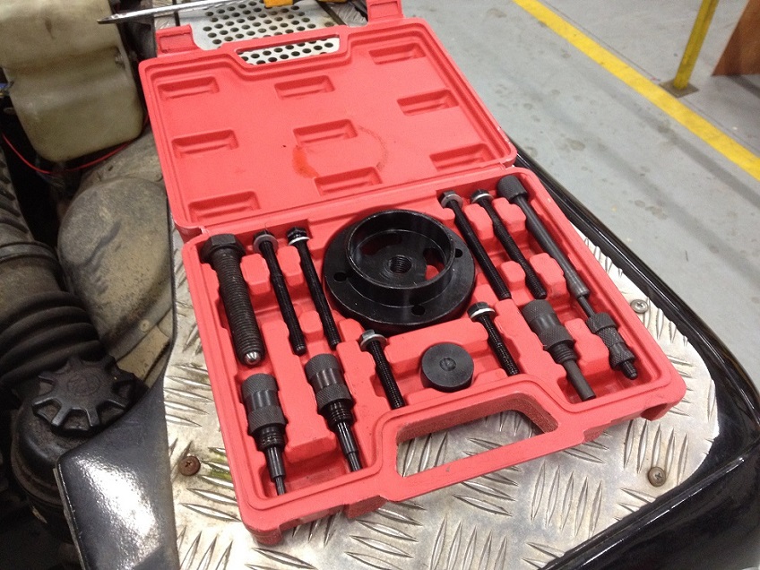
• Diesel Fuel Pump Timing Kit – similar to http://www.ebay.co.uk/itm/Pro-Land-...395?pt=LH_DefaultDomain_3&hash=item46316be18b and the good thing is the large round pulley holder is also used for pulling the crank damper off!! Brilliant for the price of about £25
• Diesel Injector Puller – similar to http://www.ebay.co.uk/itm/Professio...254?pt=LH_DefaultDomain_3&hash=item3f2ae9dd46
• Crank Holding Tool, I made mine details attached
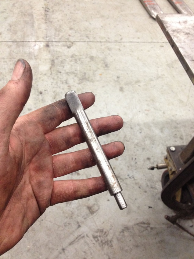
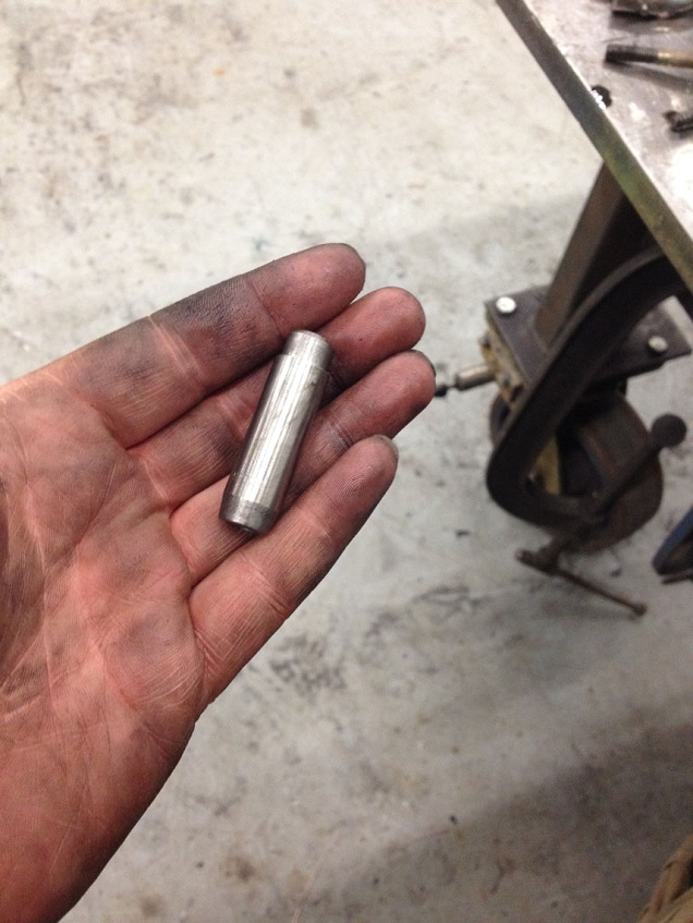
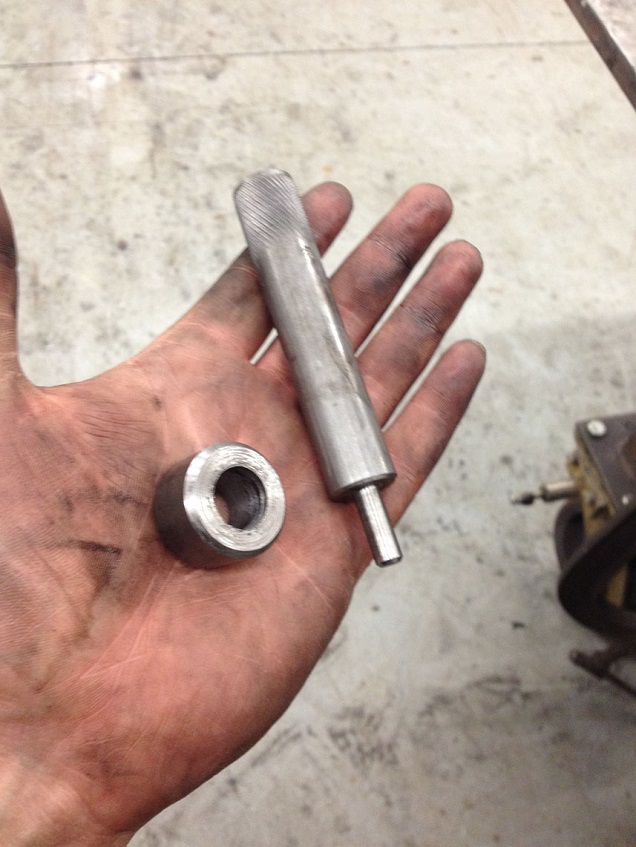
• Valve Guide Drifts LRT-12-046, LRT-12-036 and Spacer LRT-12-515…..I made mine using a lathe at work, I took the dims available from a well known tooling website and scaled the photos using AutoCAD and guesstimated the unknown dims and made the tools using some scrap material we had. Details and Dims also attached if you fancy having a go.
• All important torque wrenches and angular tightening gauge
• Dial gauge/Torsion Bar torque wrench for timing belt tensioning
Prep work:
Soak manifold bolts and turbo manifold bolts plus any other stubborn looking bolts in a penetrating fluid. Clean the areas around the injectors, glow plugs flywheel housing drain plug to prevent dirt ingress. If you are to remove the glow plugs, get the engine up to temp and loosen the plugs first, then leave over night for it to cool before starting this work.
To task:
Rember I am doing both head and timing chain, so some tasks are not required for just timing cover and vice versa, I’ll let you make your judgement on which parts to follow to achieve your result.
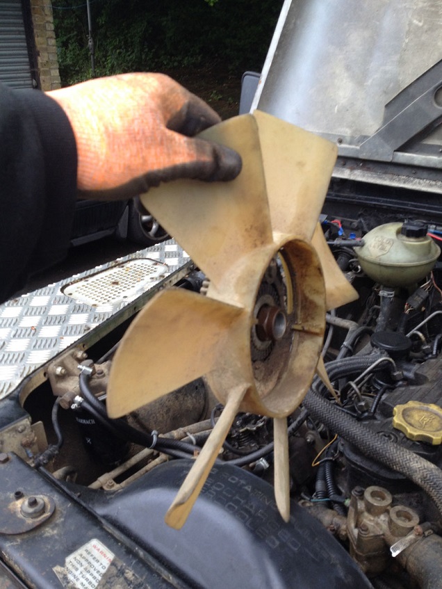
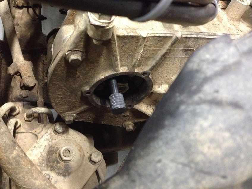
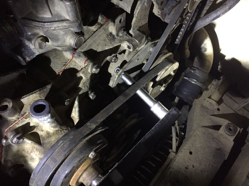
First off, remove the viscous fan. This is a left hand thread and if you are lucky it will knock off with ease. If not, place a spanner on one of the water pump pulley bolts and rotate until the spanner shaft butts up against the pump spindle and hold this spanner to retain the water pump from turning and undo the fan nut.
Remove radiator top hose and top intercooler hose
Undo the top two nuts holding the rad cowling in place and with a wiggle withdraw
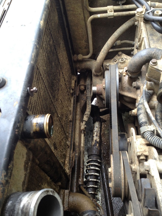
Remove the pump to stat hose and the rad bottom hose from the water pump
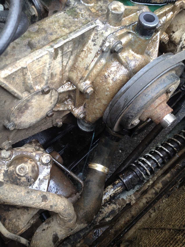
Get yer timing kit out
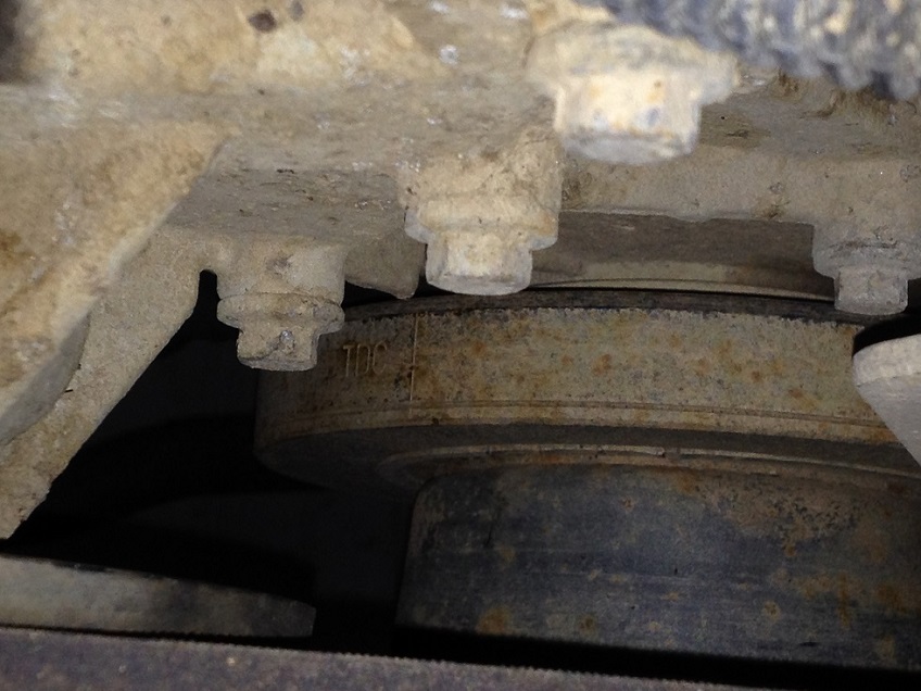
Turn the Crank to TDC as marked on the pulley and check you can correctly fit the flywheel timing pin, a wiggle with a flat screw driver may be required to line up the flywheel just-so.
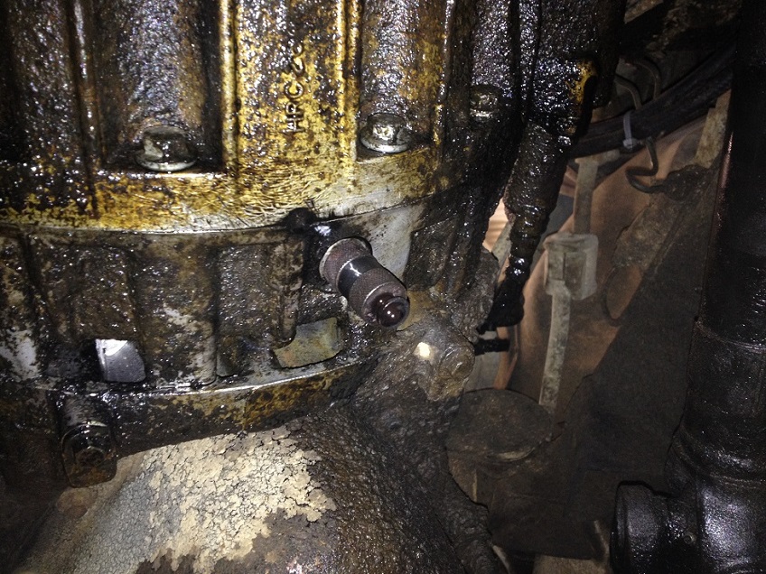
Undo the Fuel Pump pulley inspection port and wiggle the fuel pump timing pin in place, this has now set the engine in time correctly, if the fuel pump pin is tight fit, slacken the pulley adjustment bolts and using a socket and handle, turn the fuel pump a smidge until you can get the pin to fit correctly.
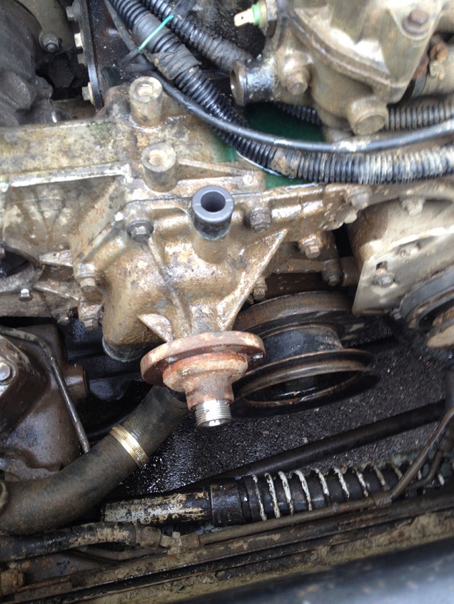
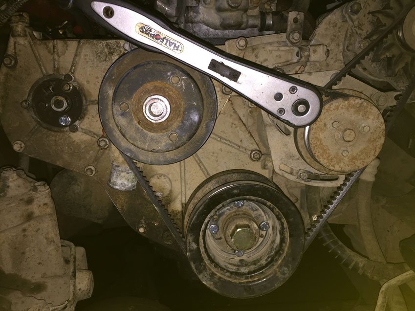
With tension on the V belts, loosen the water pump pulley bolts. Then loosen the power steering pump adjustment bolts and pivot bolt and loosen the V belt and remove along with the water pump pulley.
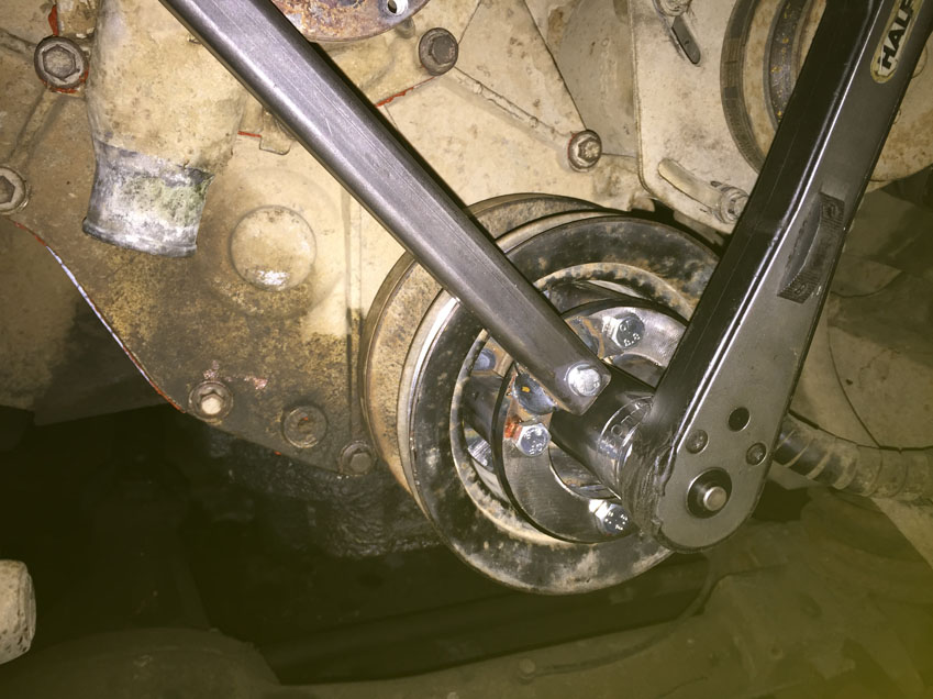
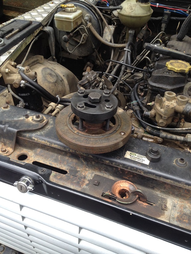
Using the Crank holding tool, sweat and bleed to undo the crank bolt…mine was looser than expected!
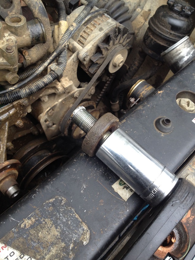
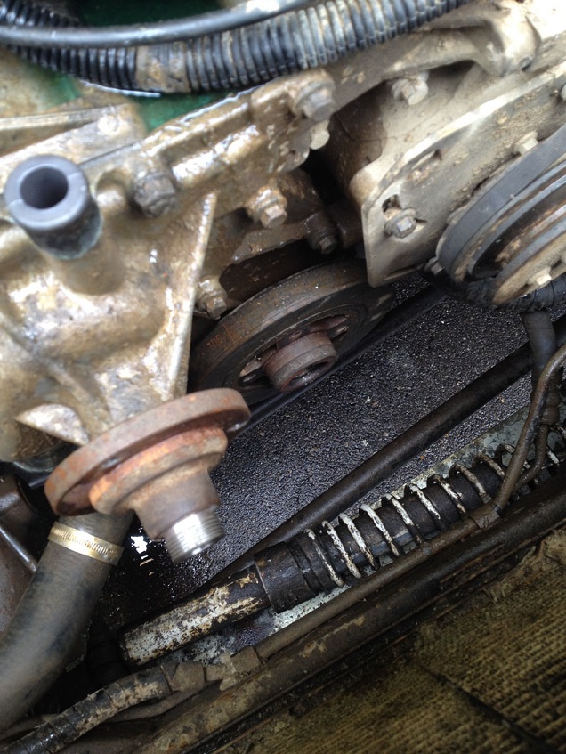
Fit the damper pulling tool from the timing kit and draw off the damper from the crank.
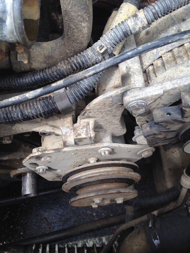
Undo the bolts surrounding the water pump and remove. Not necessary to remove the pump if you are only renewing the belt or the head etc, I removed so I could check the gasket seal. But a couple of the bolts do go through the water pump into the block so will need to be removed in order to remove the timing belt cover.
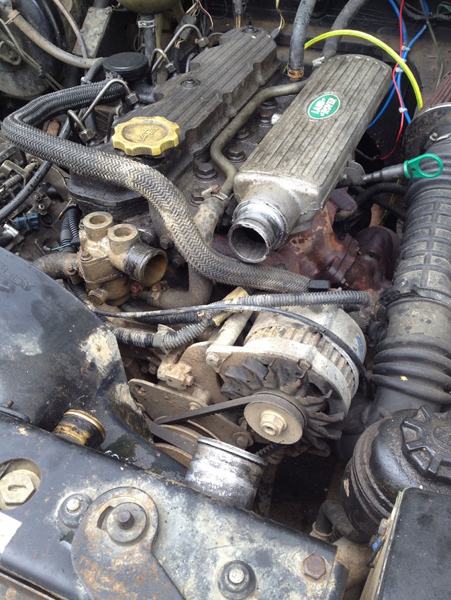
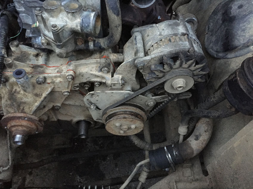
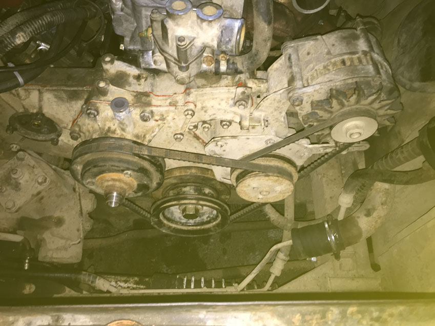
Loosen the Alternator adjustment bolts and the pivot bolt to reduce tension on the V belt, and remove belt.
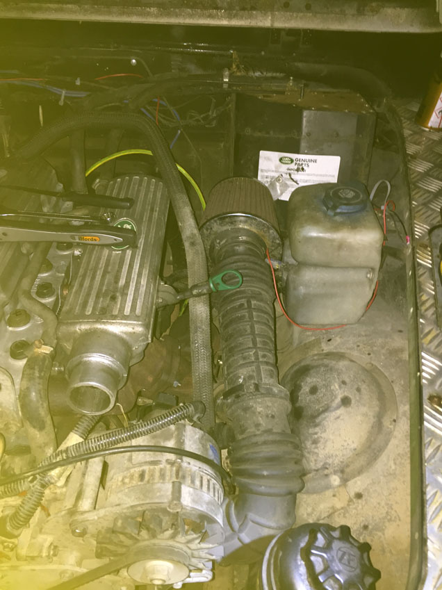
DISCONNECT THE BATTERY. Taking note of the wiring position on the Alternator (this is mine but check yours, Land Rovers have been known to be different from eachother!)
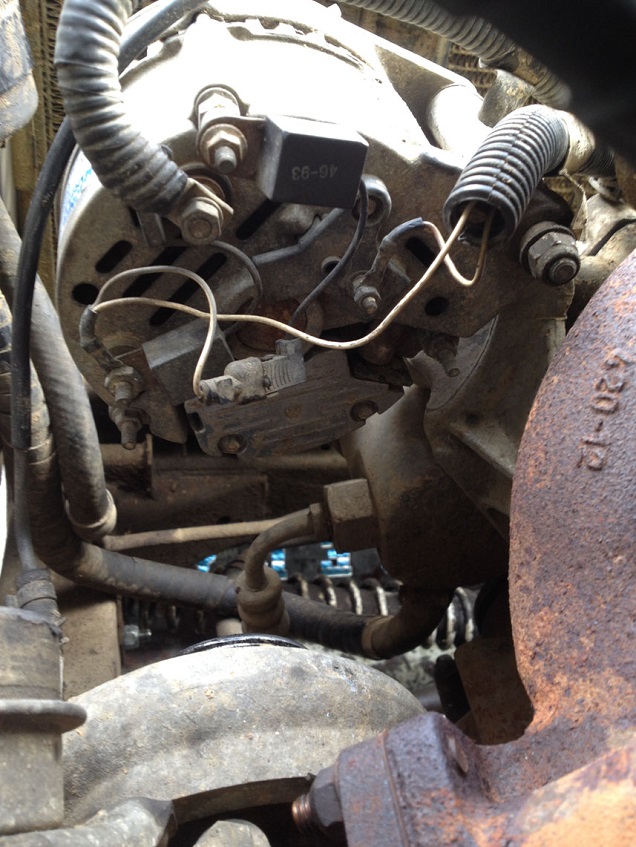
And remove the Alternator. As I was taking the head off, I took this opportunity to also remove the turbo to intercooler hose at this point.
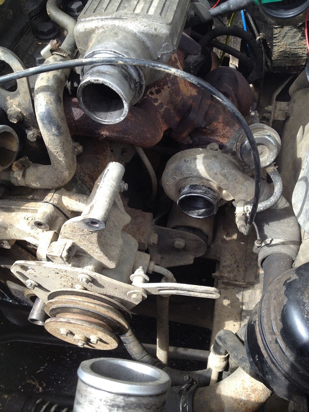
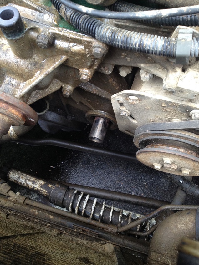
Remove the power steering pump from the bracket
Remove the bracket (2 bolts, 2 nuts)
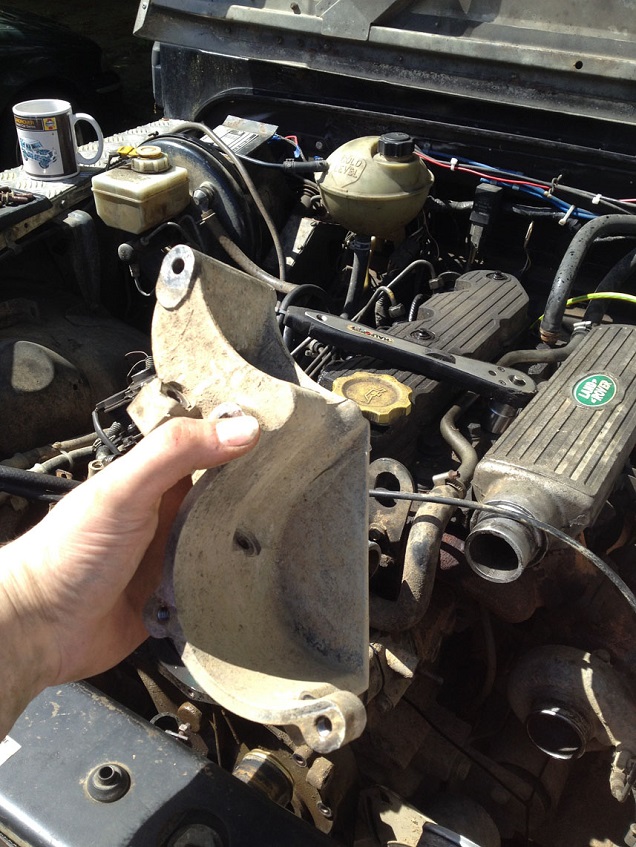
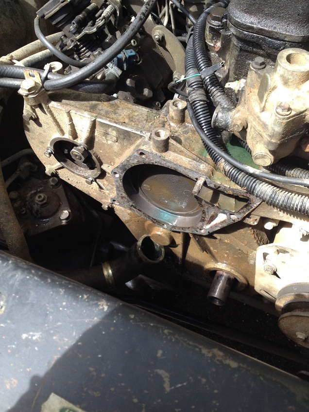
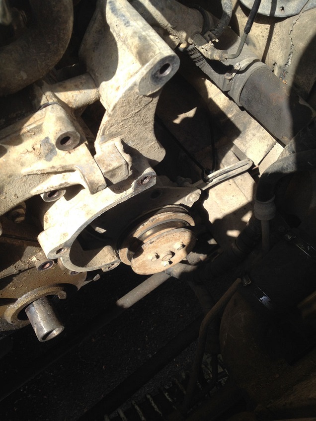
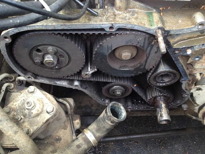
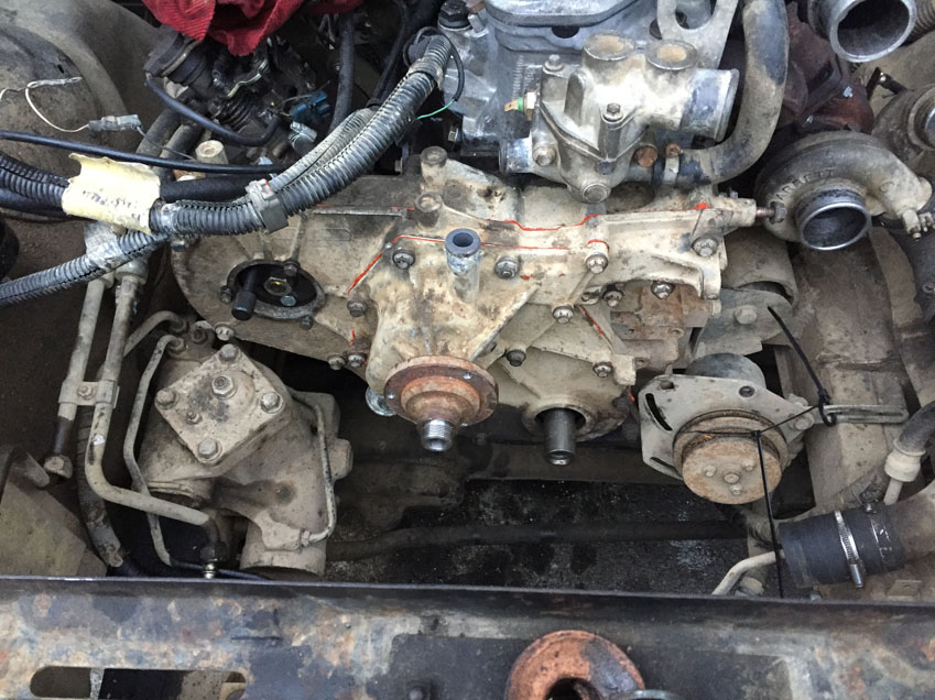
Undo the remaining bolts on the front cover and note there positions….I didn’t and it then took me a while to get the right length bolts back in the right holes again!
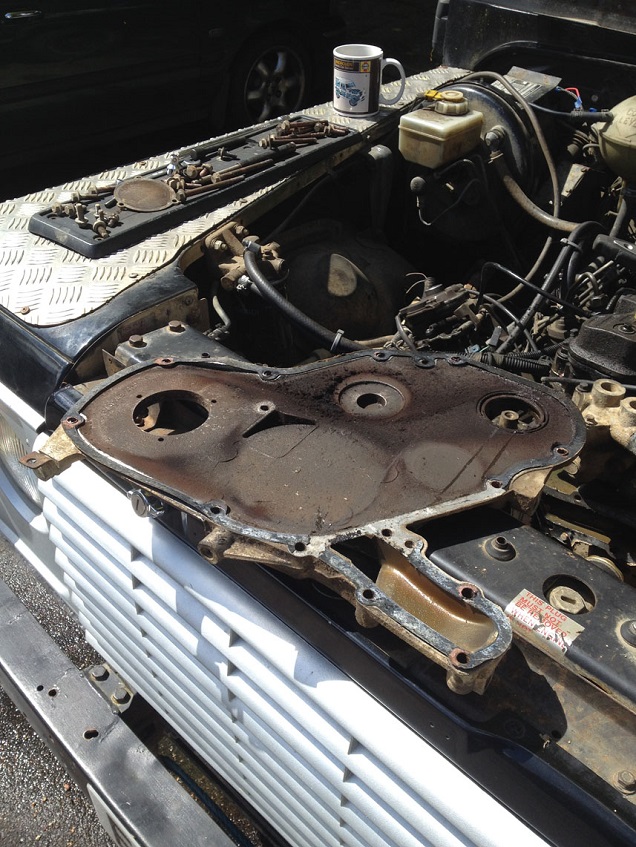
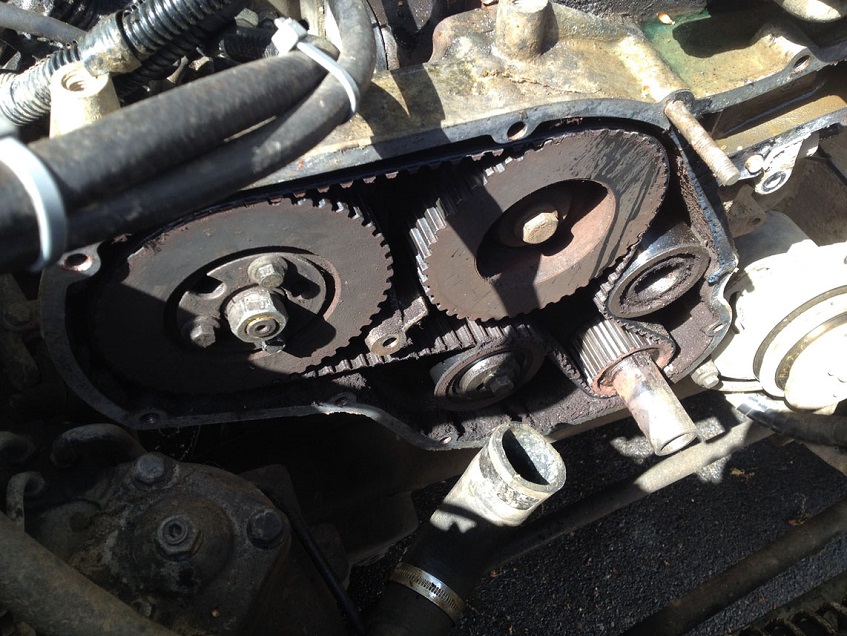
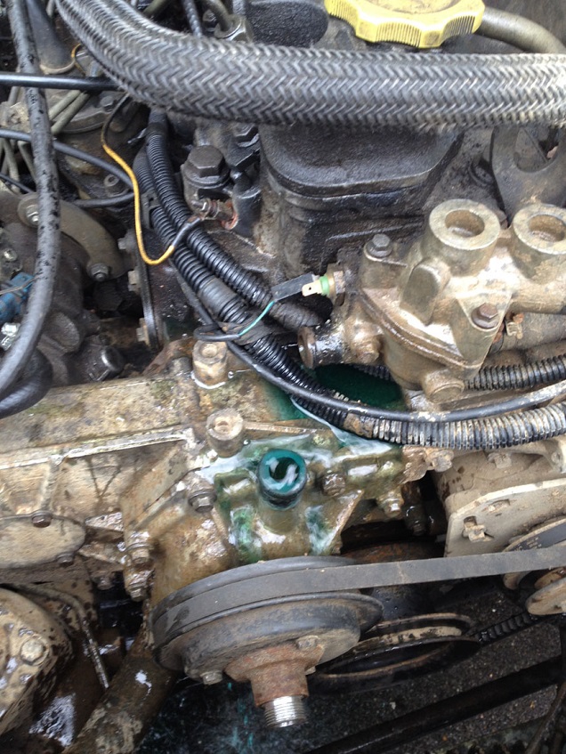
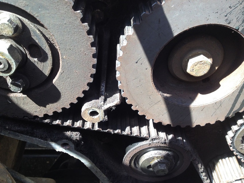
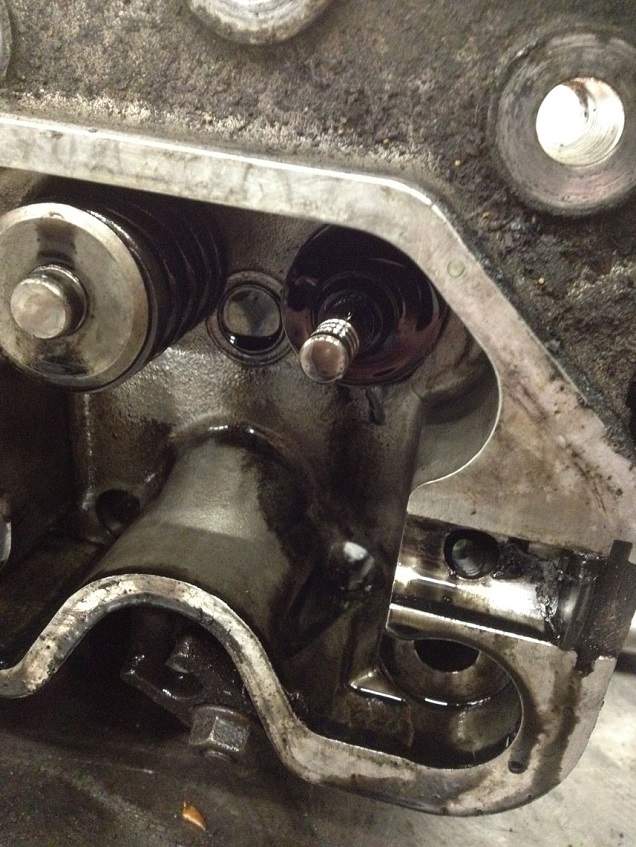
Think I have found the reason the pistons and valves met and snapped the pushrod!
If you are only doing the belt…then this is as much stripping you need to do to access the belt….carry on further down to show the belt change process and retiming and refitting etc….
I did the head too, so below is the remainder of bits and bobs to do to remove and refurb the head.
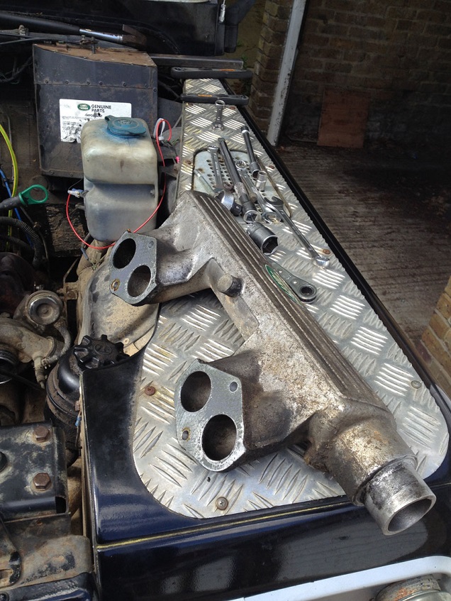
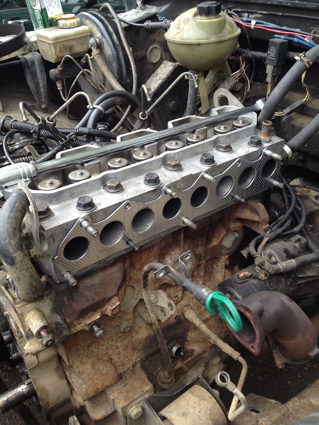
Undo the 2 long bolts and the 2 nuts and remove the intake manifold.
Remove the coolant rail.
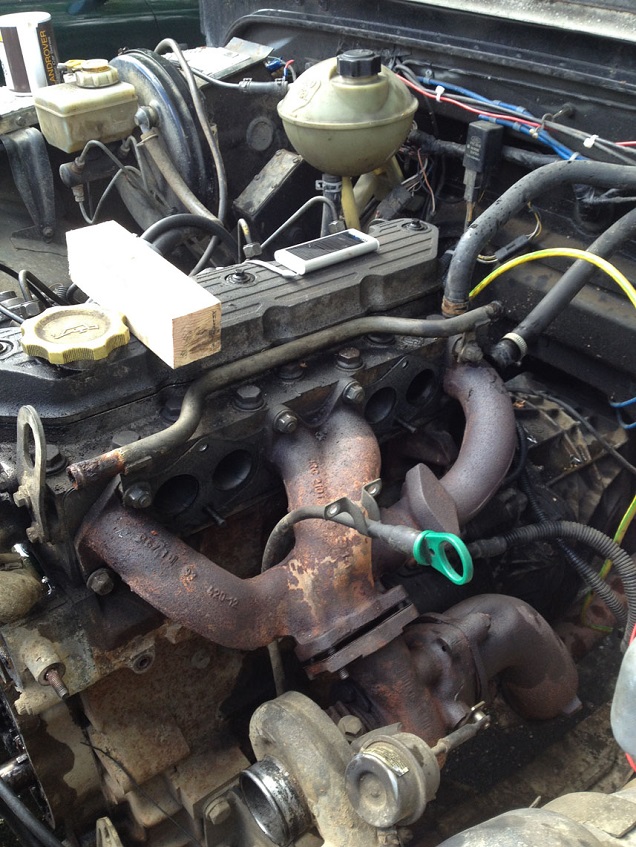
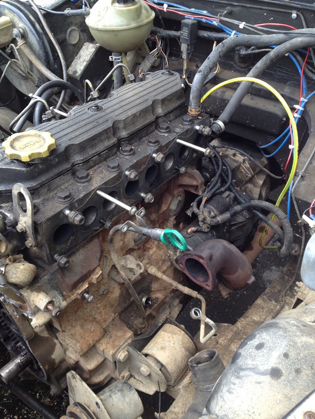
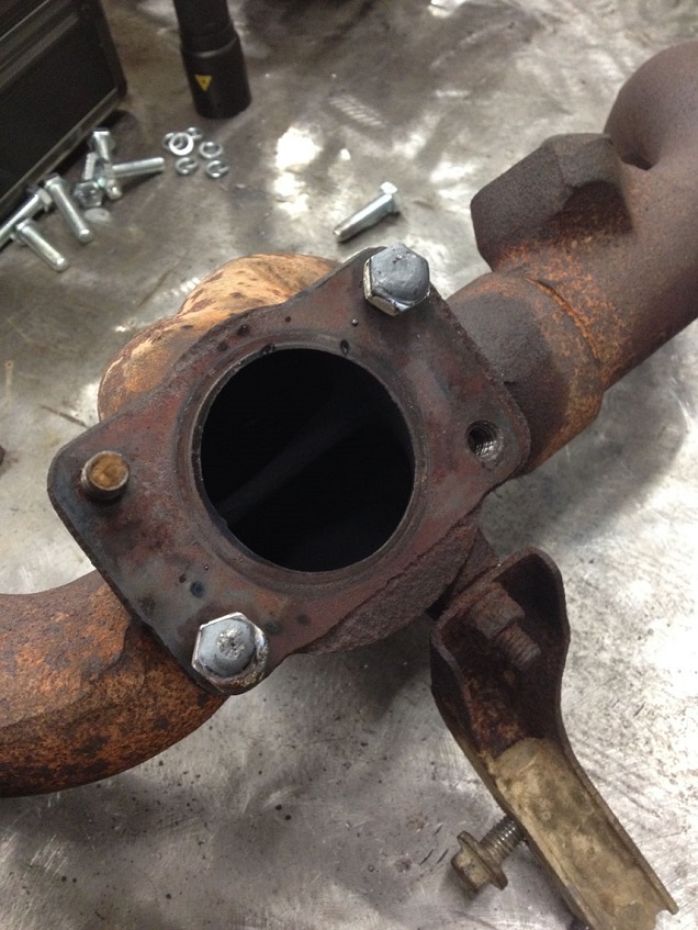
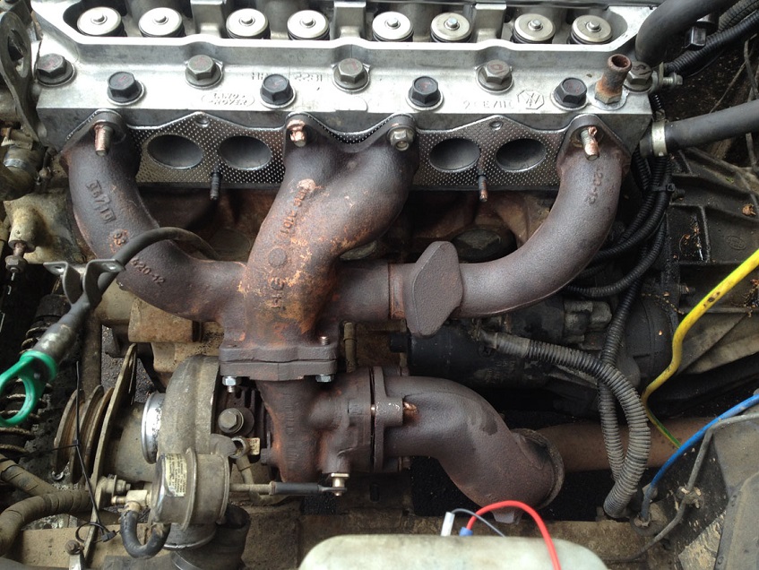
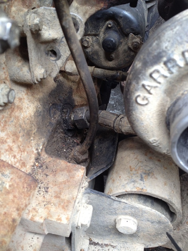
Now you have a few choices….I removed the whole turbo and exhaust manifold, but you can just either undo the manifold bolts and lever the manifold away from the head and leave in place, or remove the manifold from the turbo and the head…this is what I started to do, but the manifold to turbo studs sheared, and one I could not get off for love nor money…..so I removed the turbo along with the manifold. This involved removing the oil supply banjo to the top of the turbo and the oil return to the block and the manifold support bracket to the block.
I would advocate if possible to remove the manifold from the turbo and the head, as levering it away from the head it may get in the way, but it is your choice.
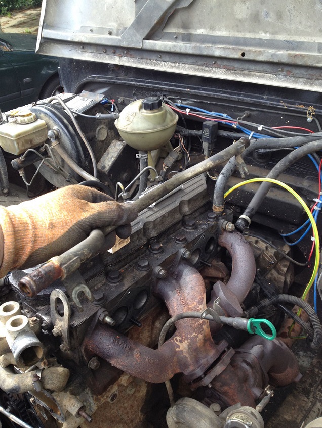
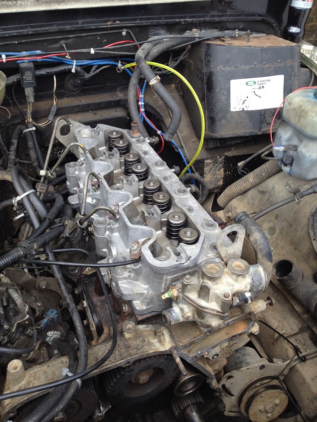
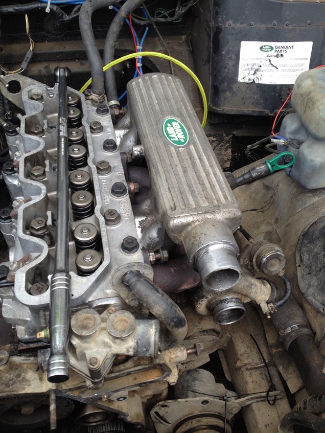
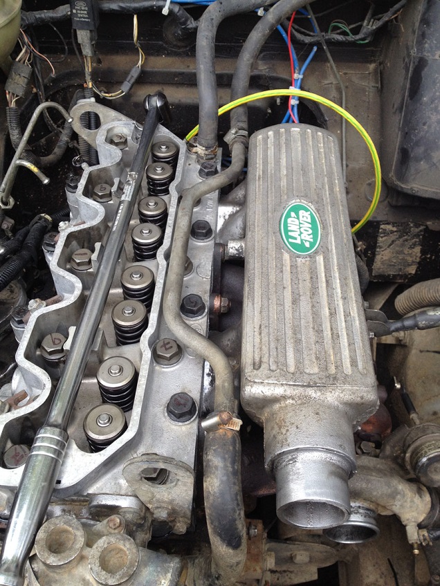
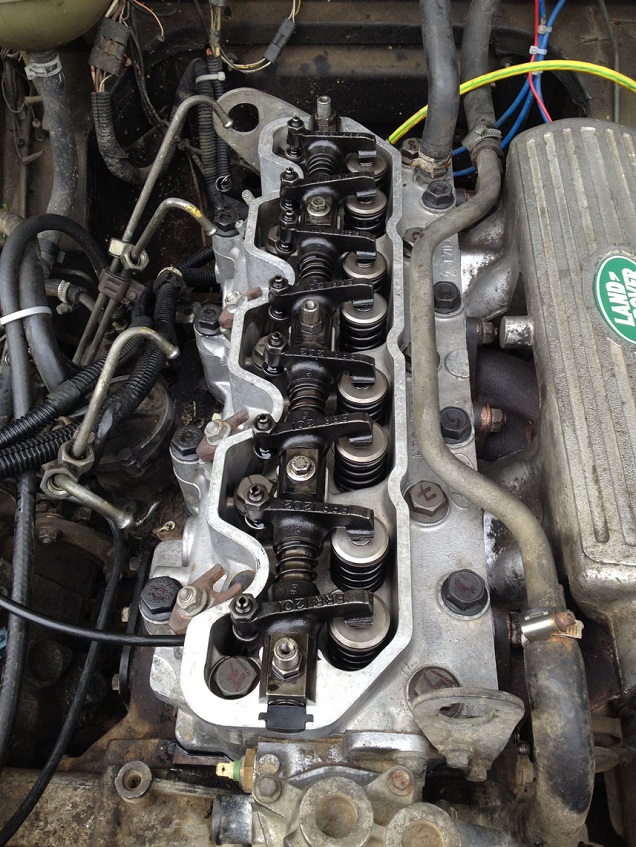
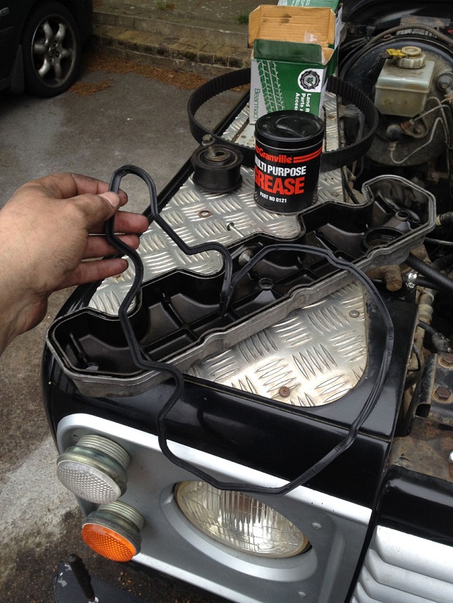
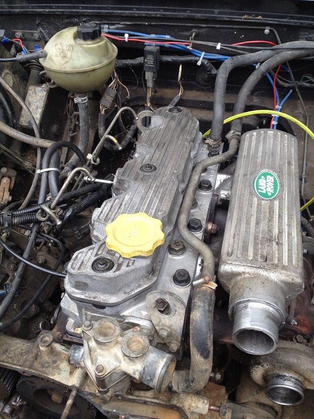
Remove the oil separator from the rocker cover and remove the cover.
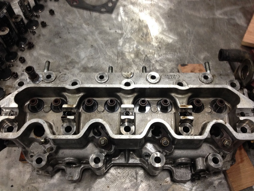
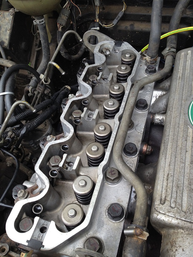
Progressively slacken the rocker shaft bolts and remove the shaft, be careful to not remove the bolts fully from the shaft as they retain the shaft retaining caps, springs, washers etc in place, so just undo them but not remove the bolts, then lift the shaft off the head with the bolts still in the shaft.
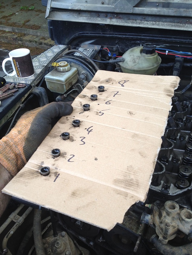
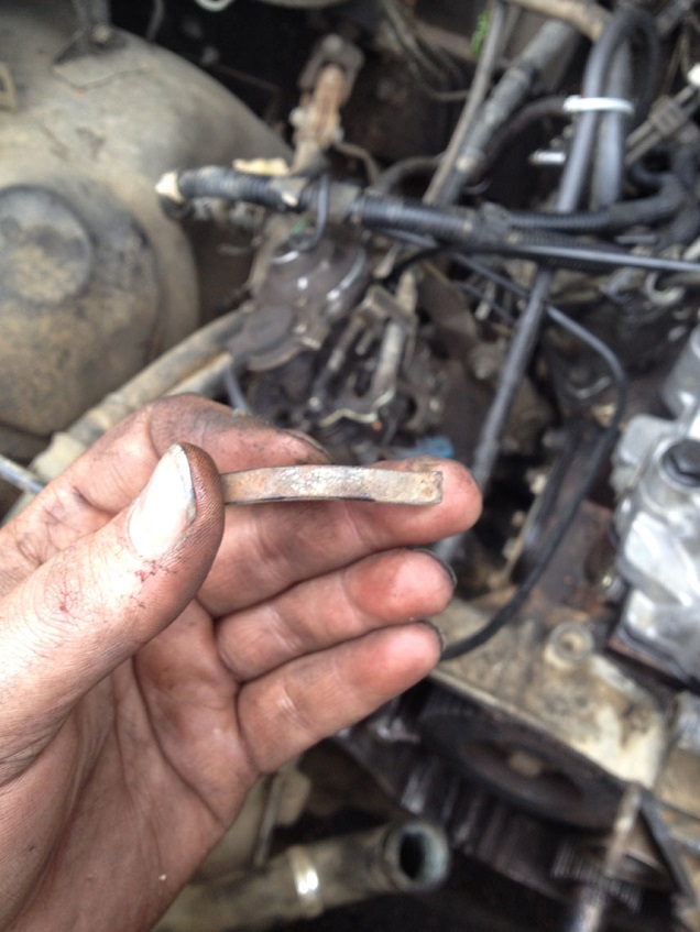
Using a piece of card numbered, pull the pushrods out and keep in order, as you’ll see No.8 on mine is missing as it had snapped.
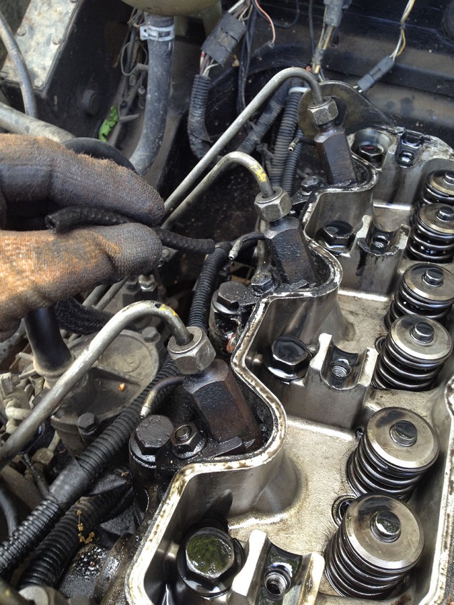
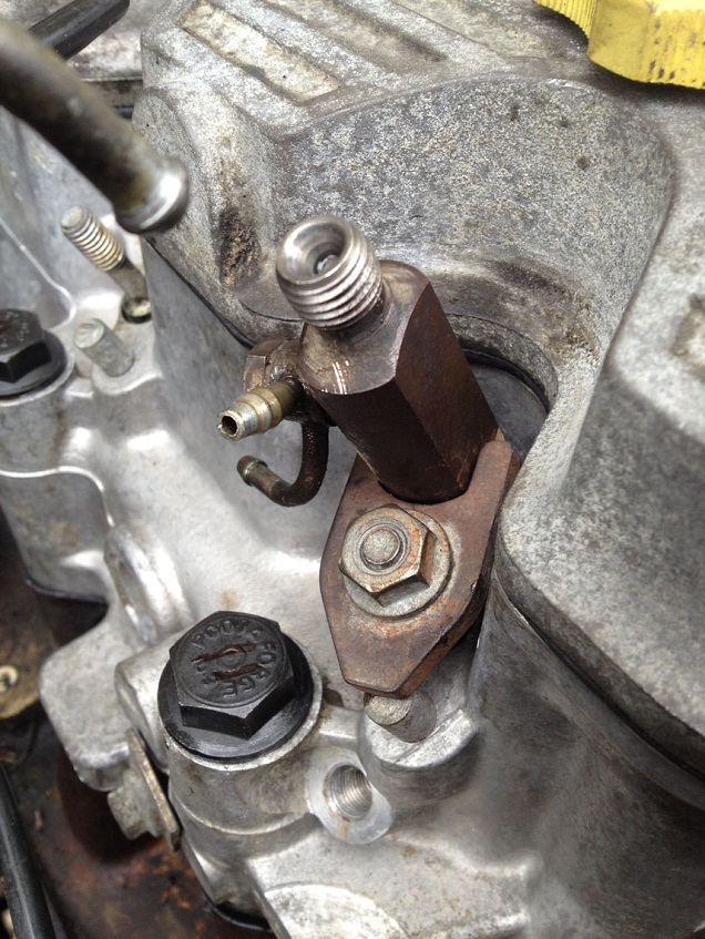
Remove the leak off pipes linking the injectors
Remove the glow plugs by first removing the electrical cable to them and carefully unscrewing from the head, they can be stubborn depending on how long they have been in there….I would advocate that BEFORE doing any of this work, run the engine up to temp and shut off, then loosen the glow plugs. Then leave too cool before starting this work, as a hot engine makes it easier at times to remove stuck glow plugs.
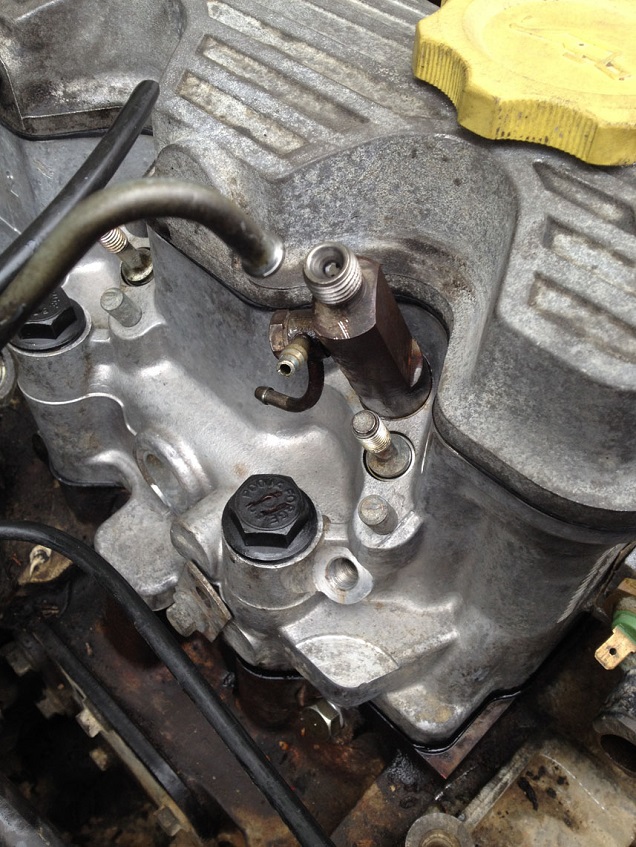
Undo the fuel unions to the top of the injectors, RAVE says to completely remove the pipes, but this is not strictly necessary.
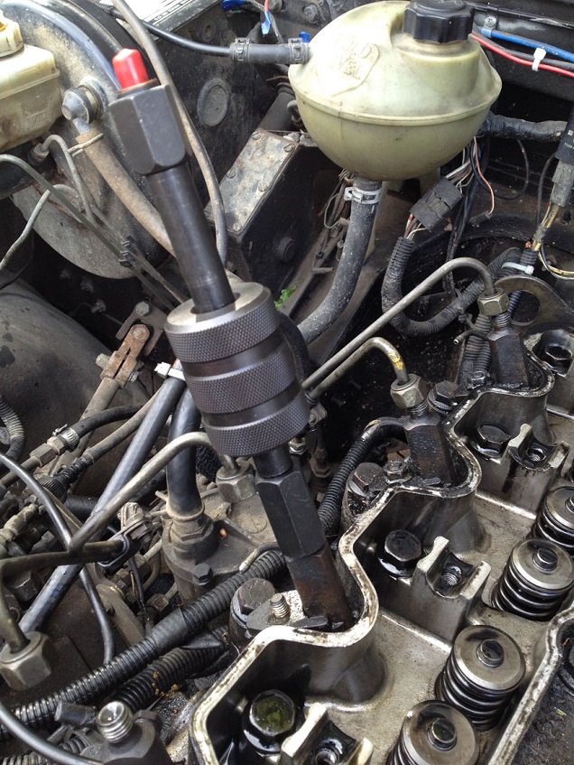
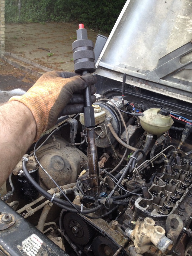
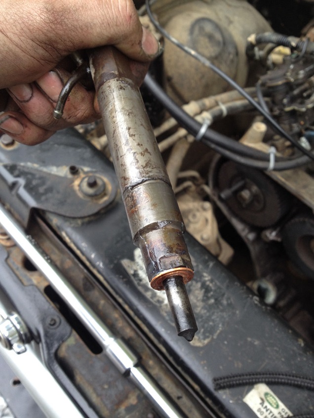
Loosen the fuel injector clamp nuts and clamps then using an injector puller (slide hammer thingy) pop the injectors out. Place in a clean dry place, in the order they were removed.
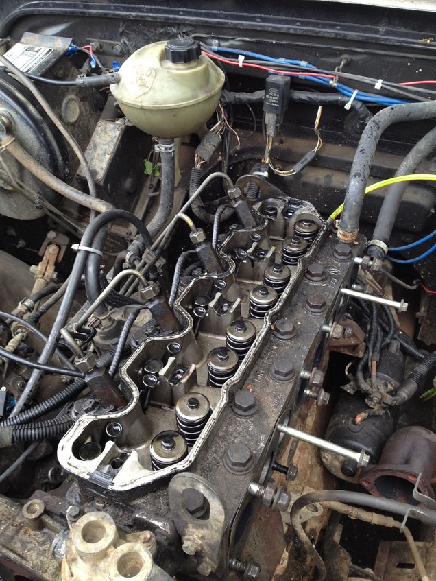
Head is now ready to be unbolted. Using the CORRECT sequence, crack off each bolt in turn, then progressively undo in sequence to prevent warping the head.
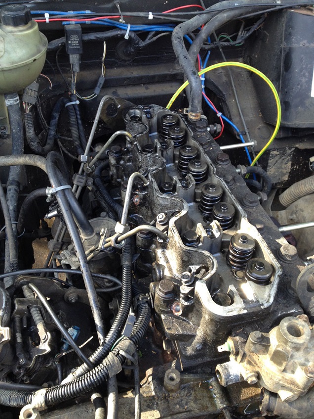
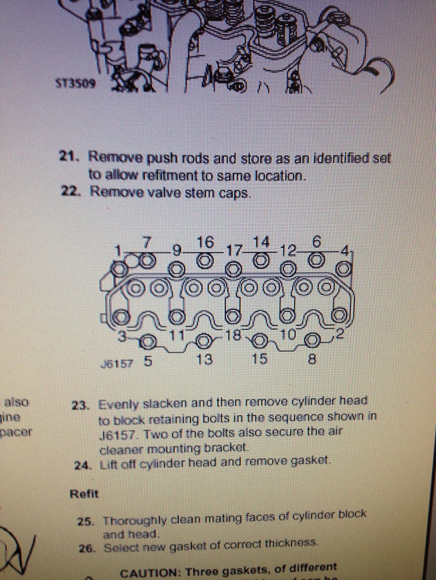
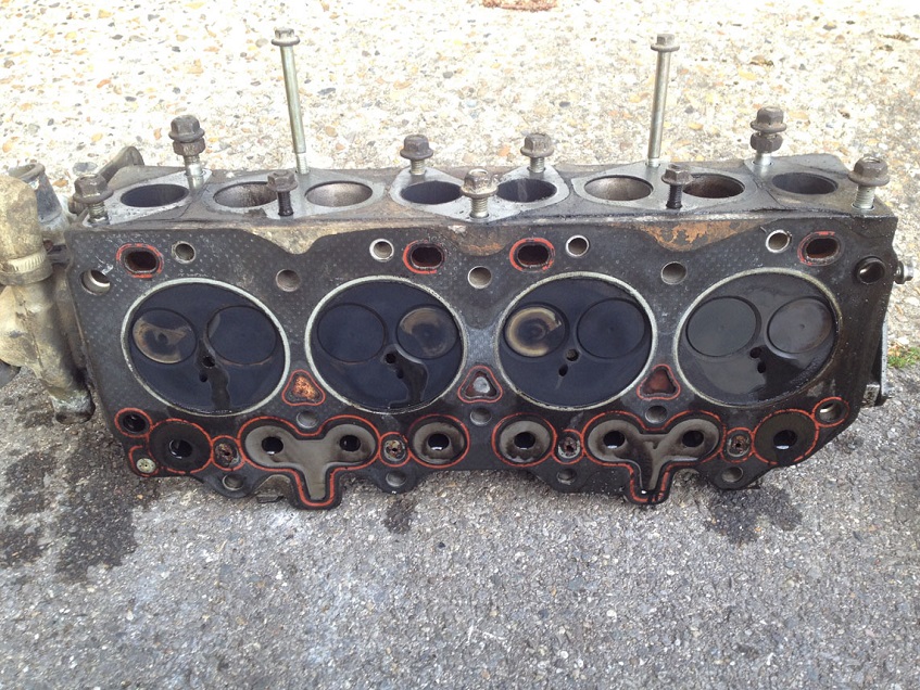
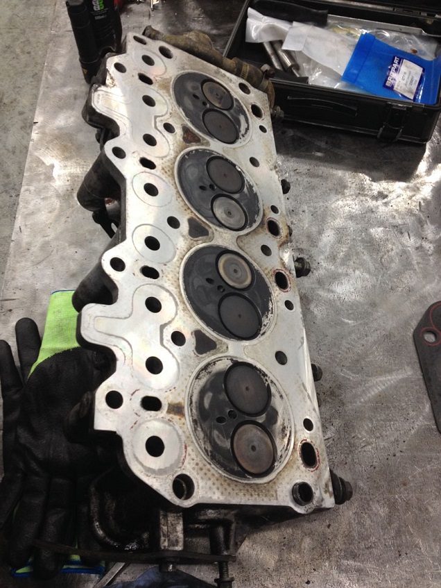
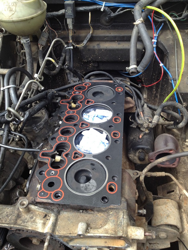
With a tiny tap to break the gasket seal (the head is located on dowels so don’t whack it sideways to much) the head should be able to be lifted off carefully.
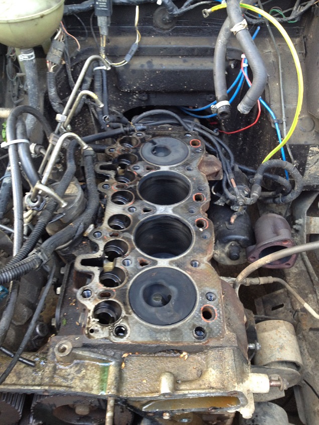
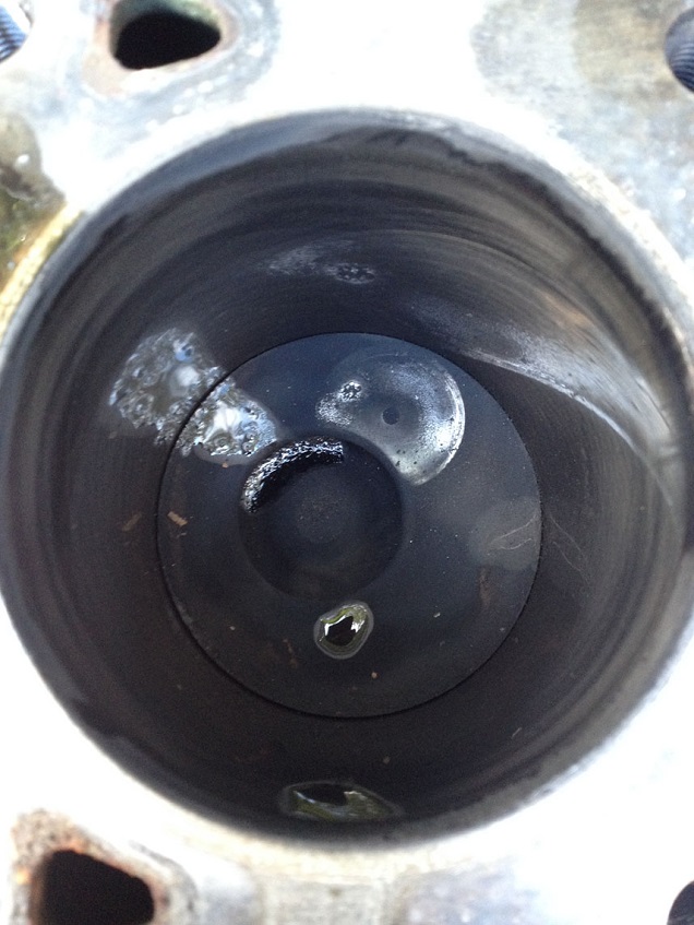
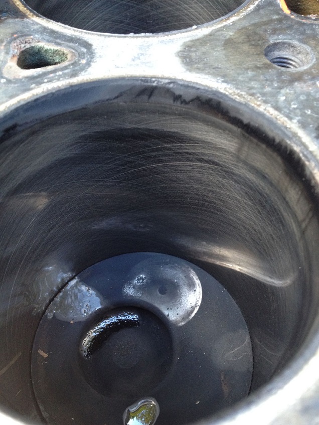
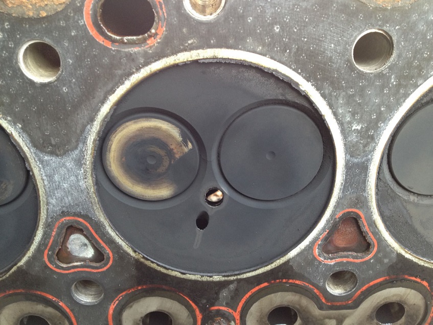
Witness marks on the piston crowns and the underside of the valves show where the valves and pistons had met, luckily they only just met and no valves were bent and the piston crowns not dented or split! (ignore the minor water spilt from the head when I removed it) Also I was pleased to see the honing marks still visible on the bores, so the engine has been looked after in is life!
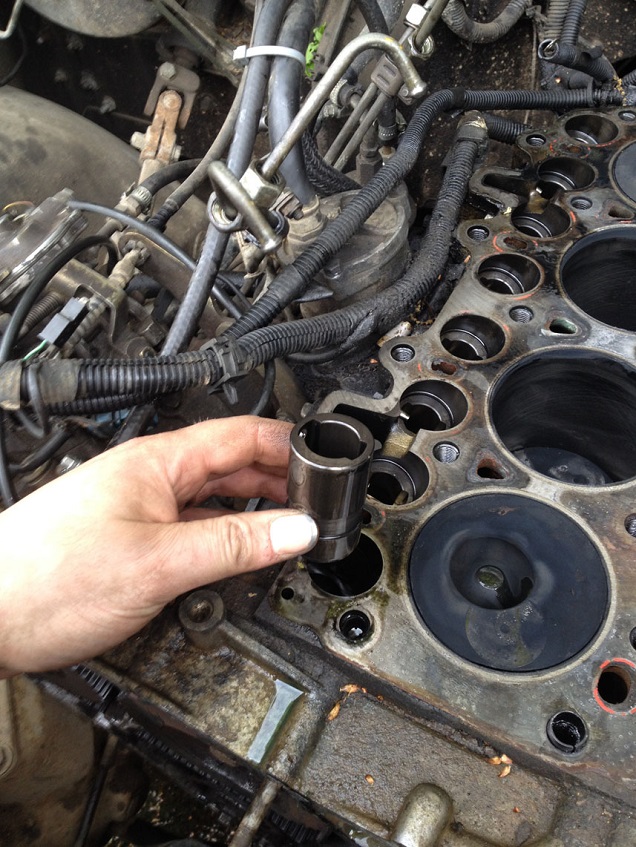
So with the head off and placed safely to one side (never rest the head on the floor with the mating side downwards else irreversible damage can be made to the valves, mating face and etc) the cam followers, slides and guides can be renewed.
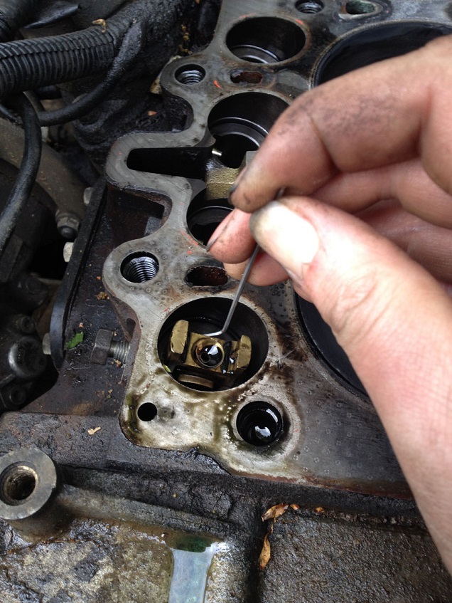
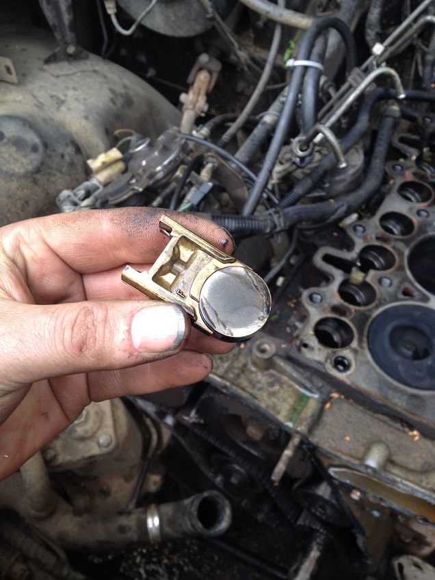
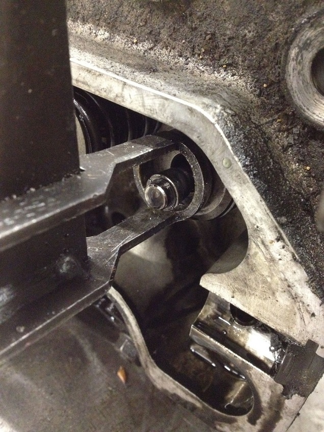
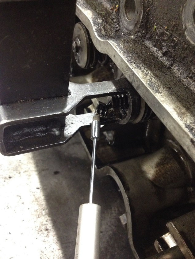
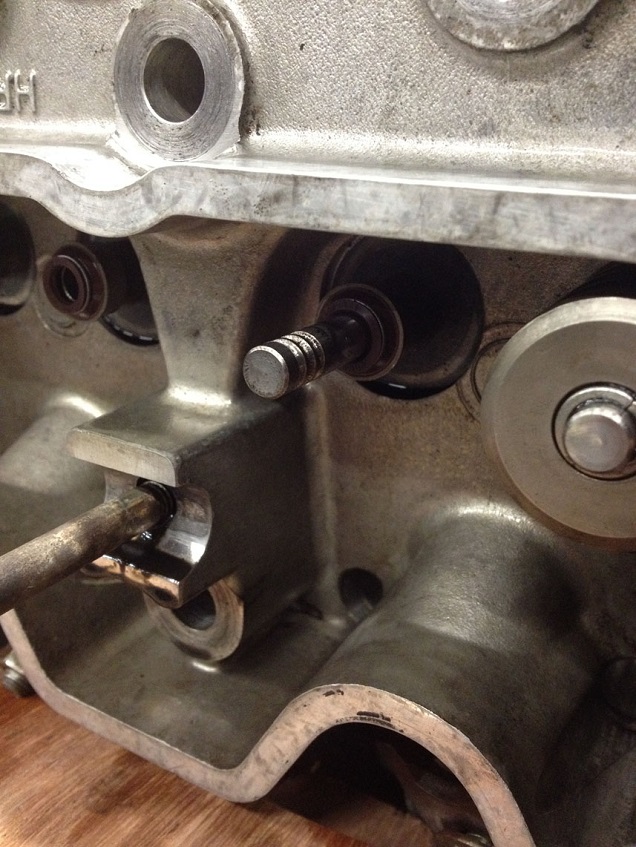
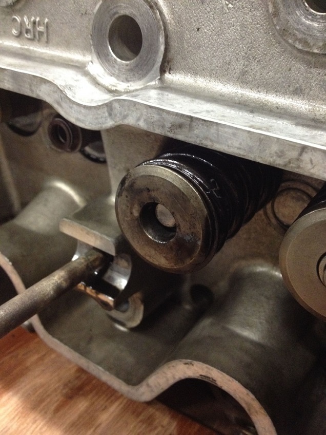
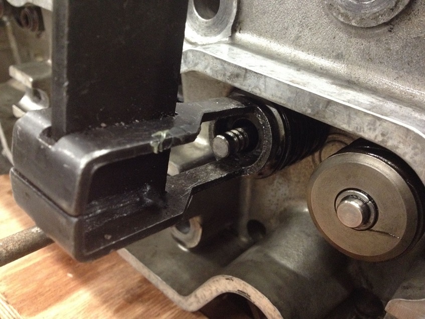
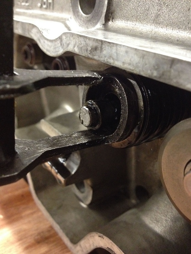
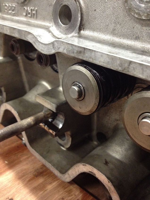
Undo the bolt on the side of the block until the little spigot is just inside the guide to prevent the guide slipping down to far, but allows the slide to be withdrawn. I used a small allen key to hook the slide and lift out, sometimes the roller follower will be attached to the slide via oil ‘suction’ and other times it will fall of the slide back to the cam (hence why the guide MUST remain in place until the slide and roller have been removed). Once the slide is removed, a long nose pair of pliers can be used to carefully withdraw the roller.
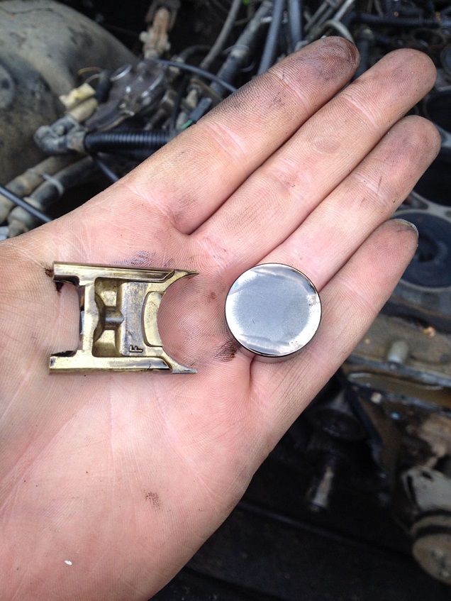
Once they are out, the guide can be removed by retaining with yer finger and removing the bolt on the side fully.
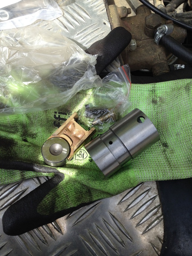
Replace with new in the reverse fashion, guide first then roller and the slide (note the slides have an F on front face….replace with this F facing the front of the engine)
One bolt is in a silly place, so you’ll need to remove the socket cap to withdraw the bolt
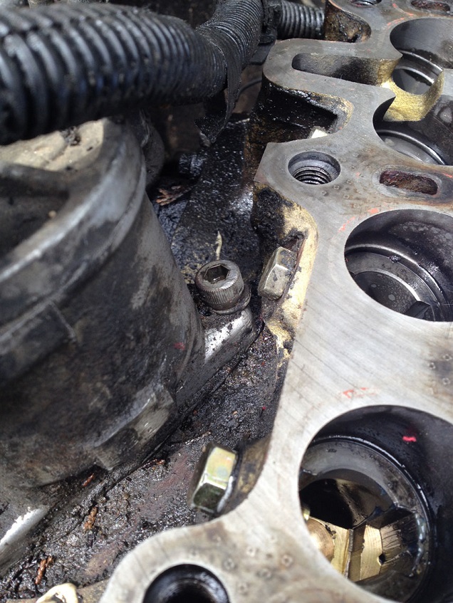
Cover the open bores and piston crowns with rags stuffed in the open holes, and I place a piece of wood over the top of the block so no damage can be made to the mating surfaces while I did the rest of the work.
So, if you are just doing the timing belt…carry on from here! Head refurb will follow the belt replacement instructions!
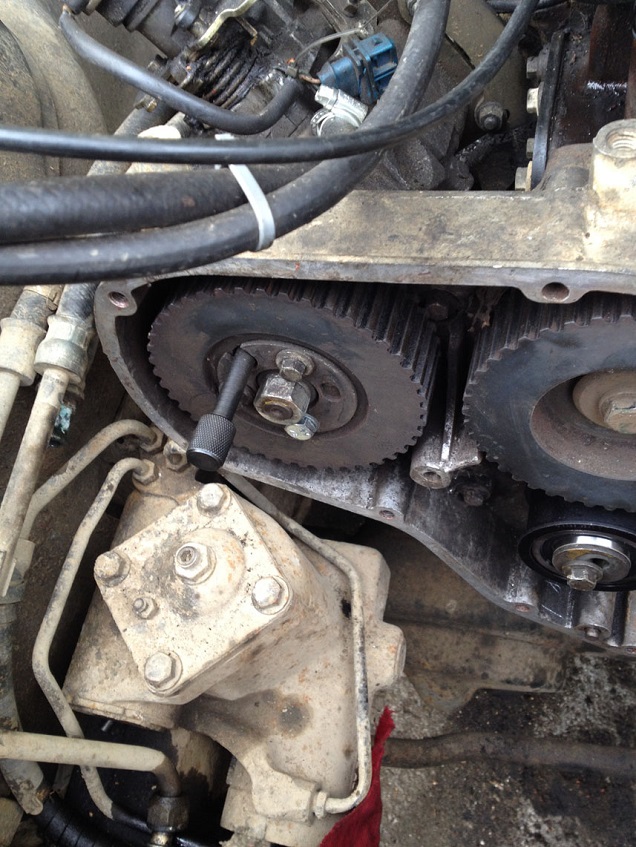
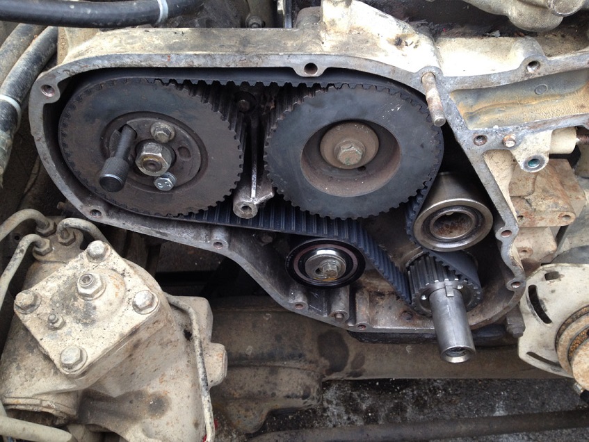
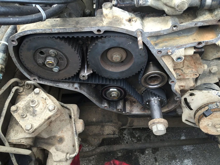
Remove the tensioner
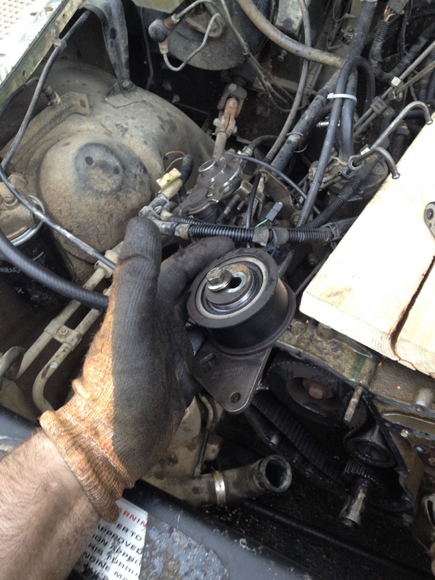
The belt can now be removed (you must make sure the timing pins are installed and remain installed while the belt is off.)
If you are replacing the idler, you can now remove that too.
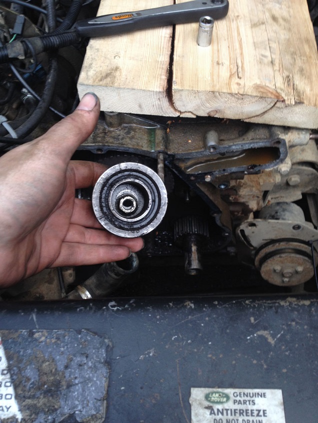
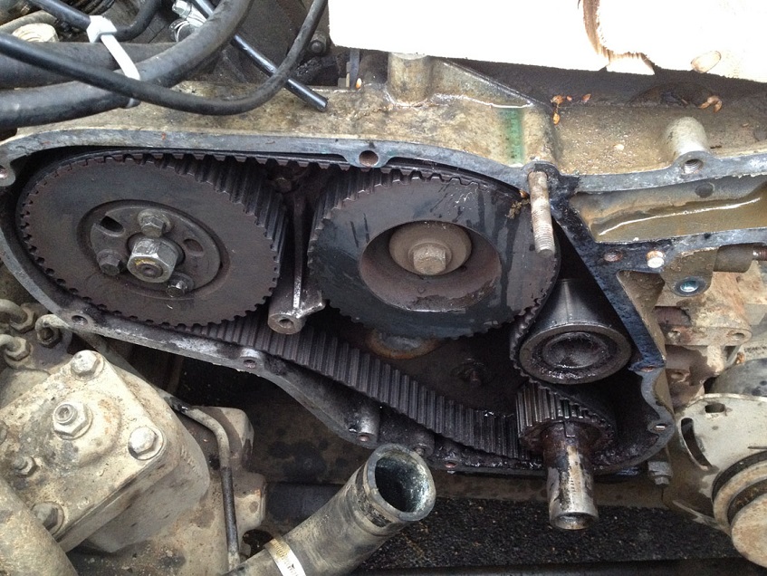
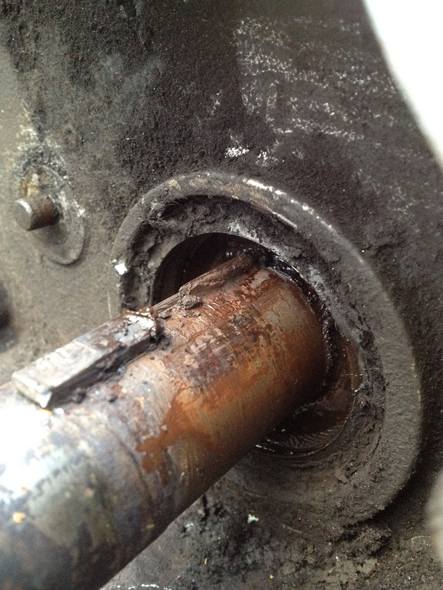
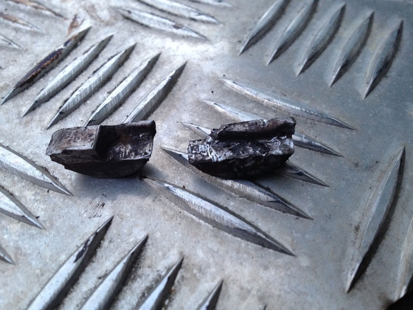
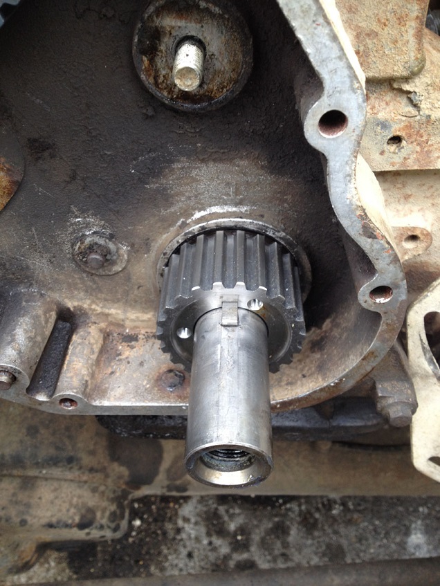
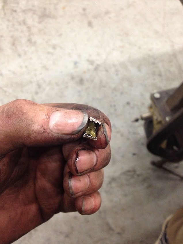
Found the reason my cam and pump timing was out….
If you have been following my other threads, you not this was a bit of a mystery, until I removed the sprocket and found the horror.
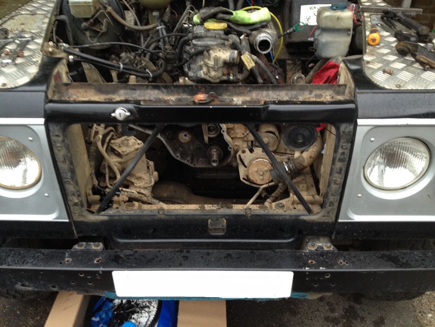
In order for me to remove the sprocket as mine was fubar’d I needed to remove the rad, intercooler and oil cooler….
No photos of this, sorry, but it is basically, remove the oil unions to the side of the rad and catch any spilt oil, remove the lower intercooler hose, top and bottom hoses were already undone. Undo the 4 bolts holding the retaining plates to the slam panel and then lift the whole rad/intercooler assembly out in one lump
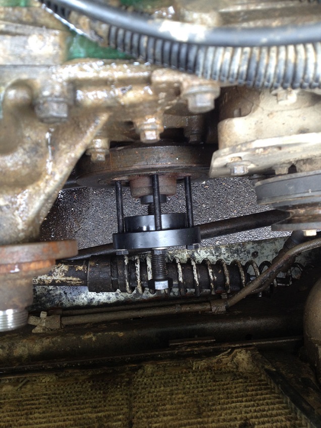
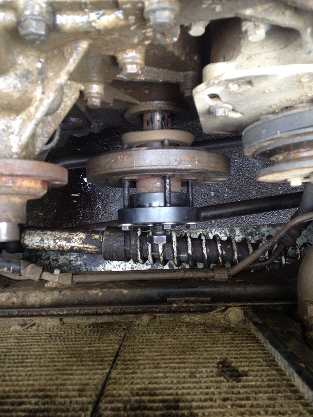
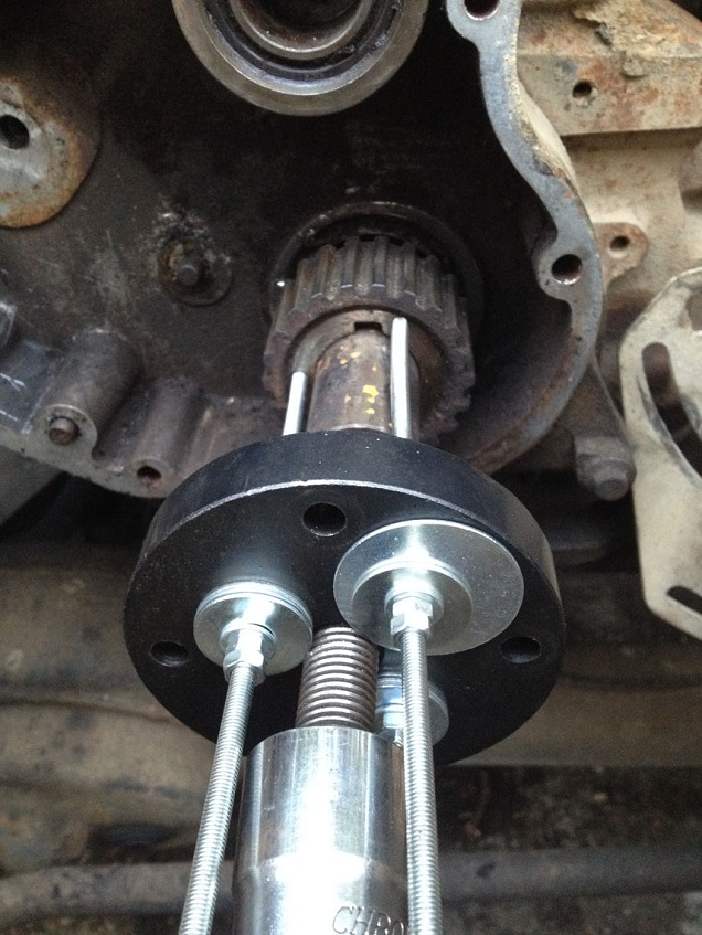
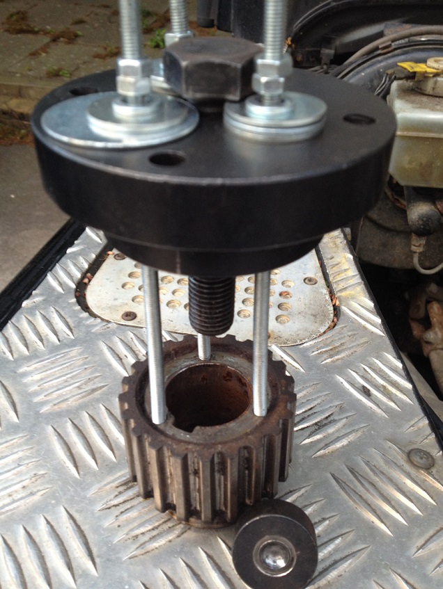
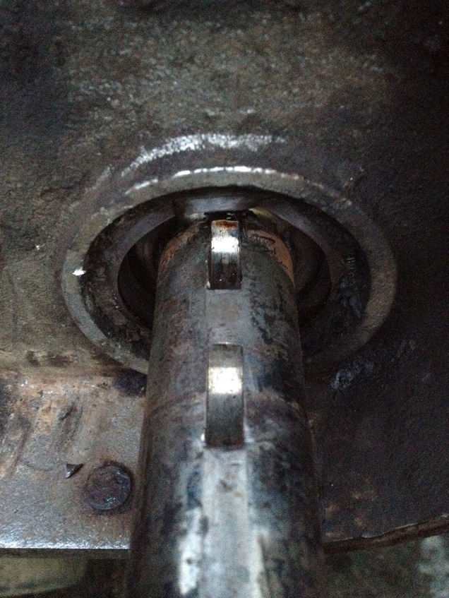
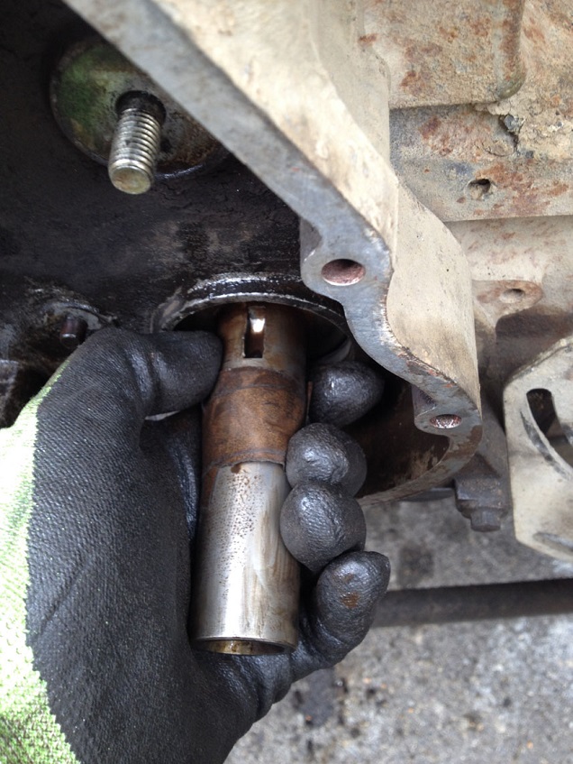
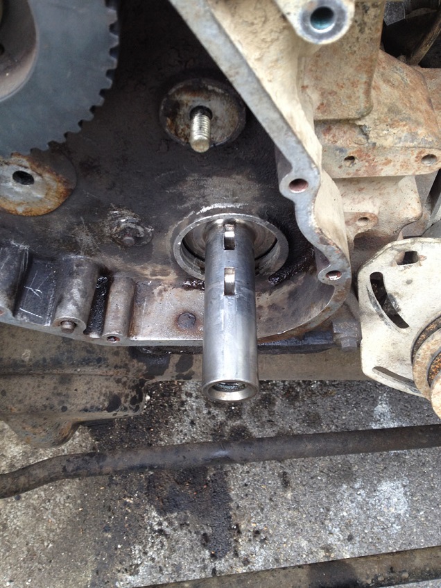
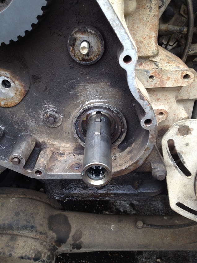
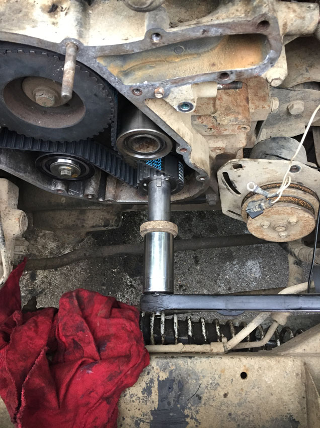
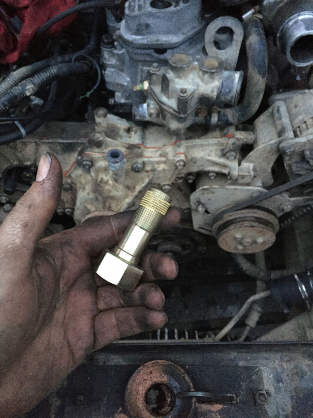
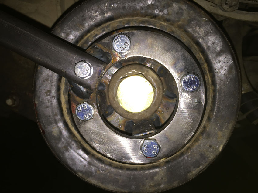
Using a makeshift puller from the timing kit and some M5 studding, pull the sprocket off the crankshaft.
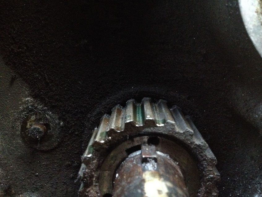
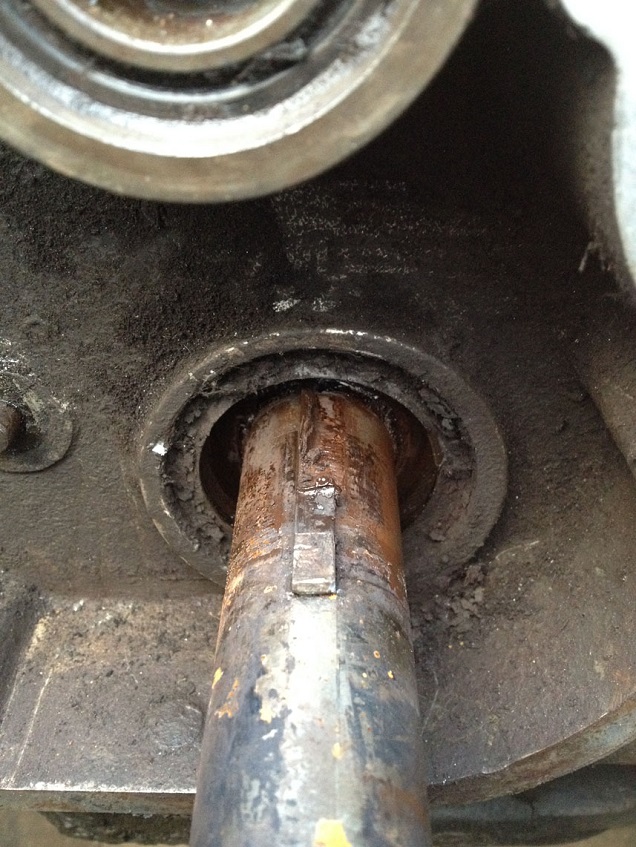
To discover my horror underneath!
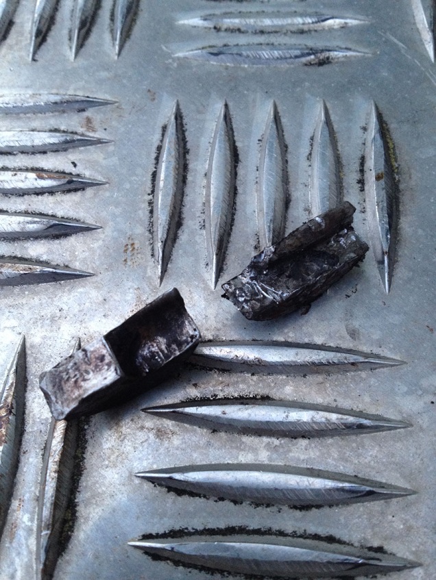
Knock the woodruff keys out (replace them anyway even if yours look fine)
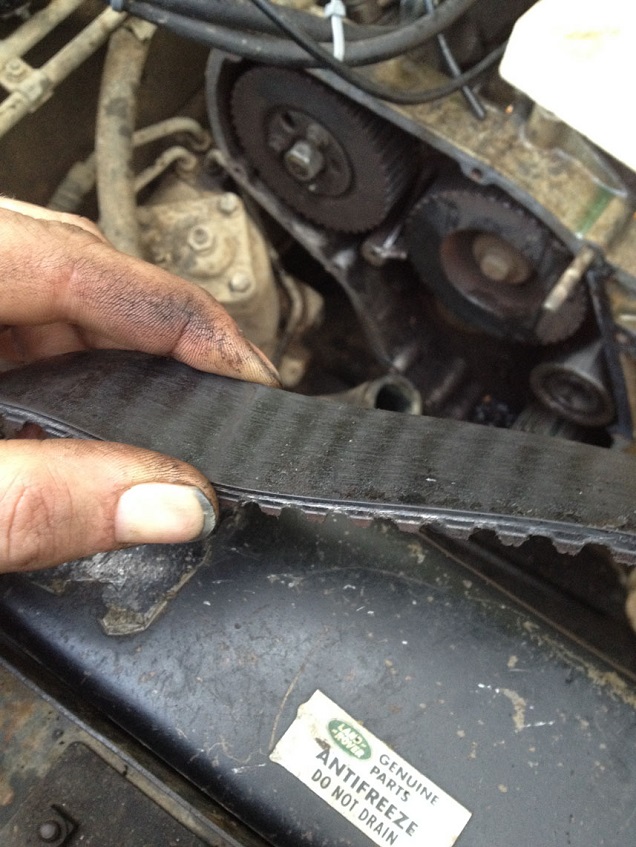
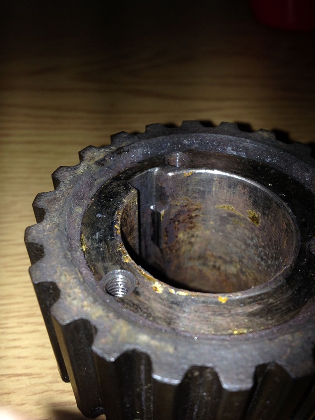
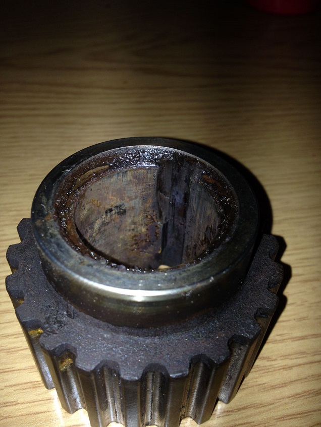
Check the sprocket for wear and replace as I had too..!!
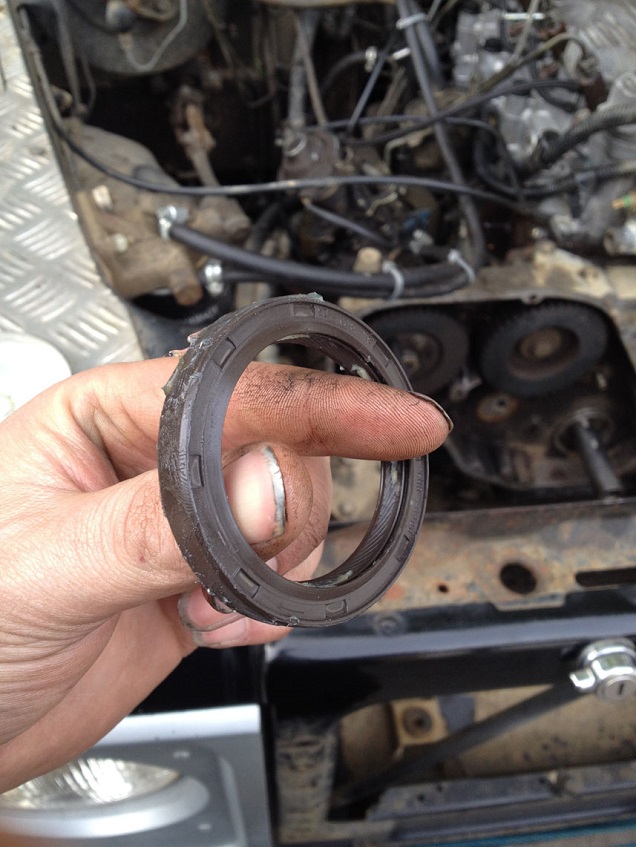
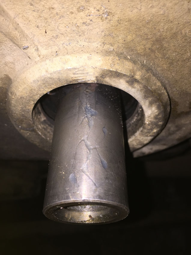
NOTE the depth of seal engagement into the rear of the timing case and then remove the crankshaft seal using a seal puller or a large flat screwdriver
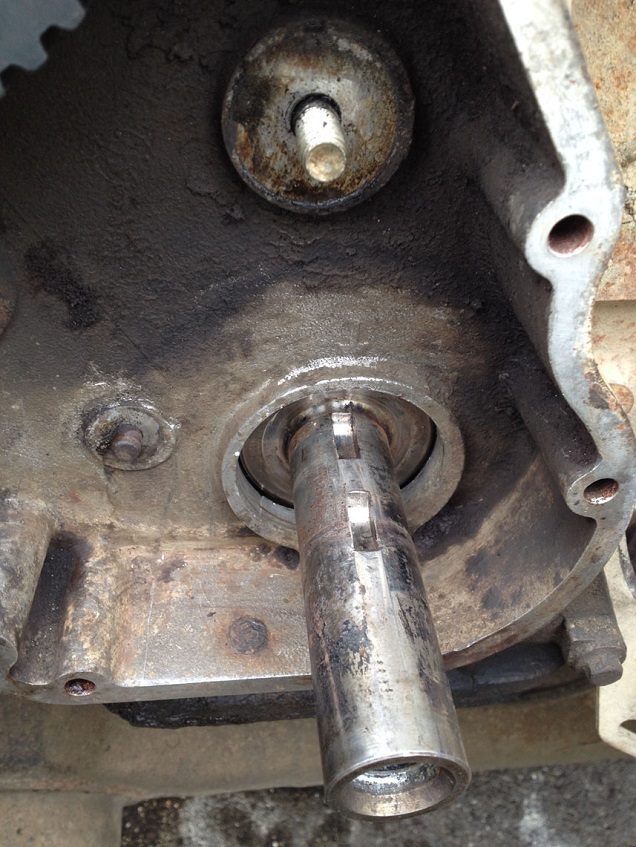
Using some wet/dry paper and some lube (I used WD40) clean the crankshaft end
Grease up a new crank seal and fit in place, I used a length of tube of suitable diameter to seat the seal in the correct depth, but very careful drifting with a block wood will do the job, just try to keep it square as it goes in.
Replace the woodruff keys and slide the crank timing sprocket in to place and drift in to position
Fit the new idler, realign the Camshaft pulley gear correctly and thread the belt into position keeping tension on the belt as it comes off the crank sprocket, round the idler, over the cam sprocket….when you get to the fuel pump pulley (the locking pin should still be engaged), ensure it is loose and turned to roughly halfway of its travel, then thread the belt tightly over the top of the pulley allowing the pulley to rotate slightly so the teeth and belt align.
Then fit the tensioner into position, but refrain from doing up the bolt fully.
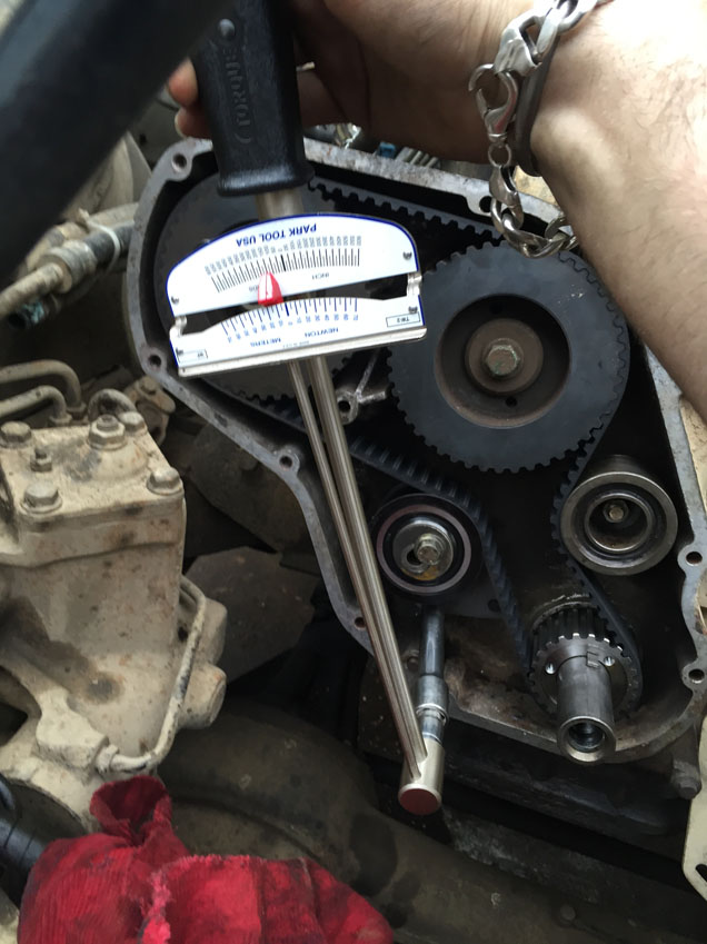
Now you must use a dial gauge/torsion bar style torque wrench to set the tension on the belt, a clicky torque wrench will not do the tension correctly.
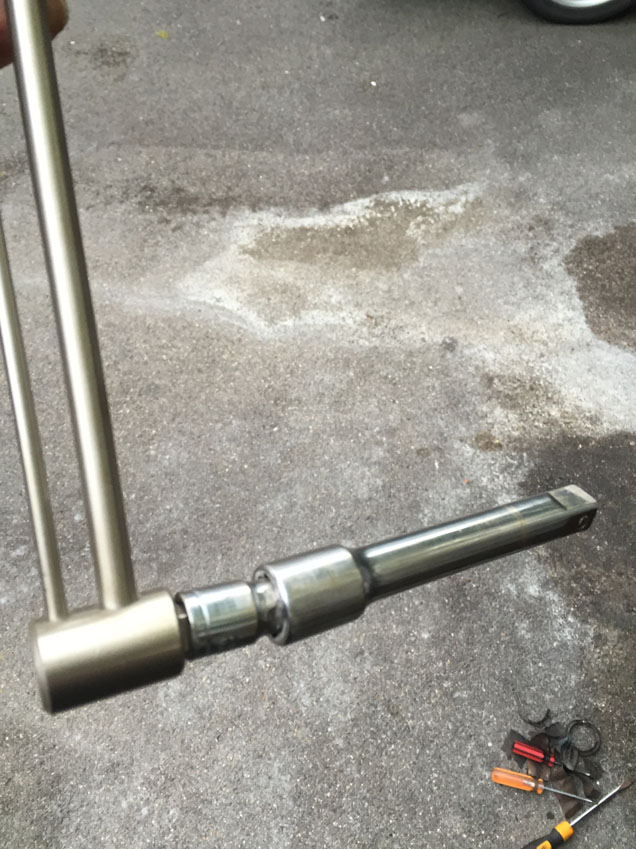
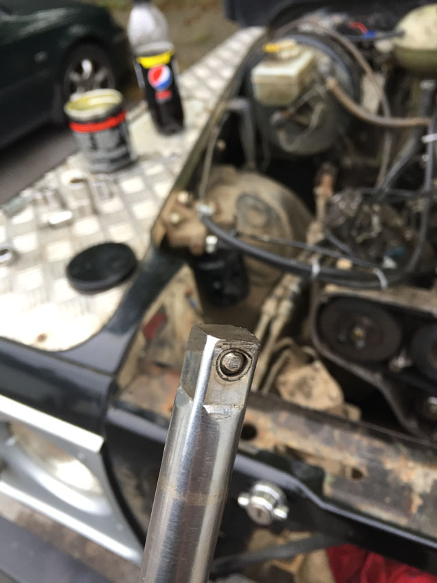
I got mine from Halfords, made by Parker Tools and cost about £40….the downer is, it comes with a 3/8” drive and the tensioner is a 1/2" square hole!
Not having time to go back to work to make a proper adaptor, I hammered an 8mm 3/8” drive socket into the end of a 1/2" drive extension, then ground the end of the extension to a flatter finish as the rounded end kept jumping out of the locating hole.
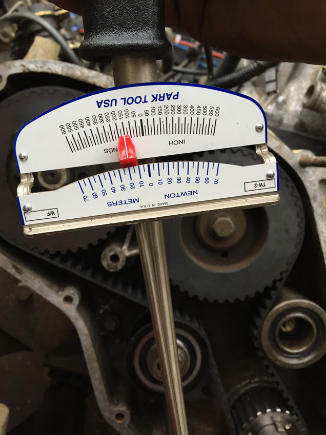
Apply tension to the belt to a reading of approx 18Nm (for a new belt) and tighten the tensioner bolt. Check RAVE for tension.
Install the crank bolt, and do up the fuel pump pulley adjuster bolts.
Remove the fly wheel timing pin and the fuel pump timing pin and rotate the crank CLOCKWISE TWICE, and return to TDC
Refit the timing pins, and loosen the fuel pump pulley adjuster bolts again, loosen the tensioner, and retension the belt using the above method again, and tighten the tensioner bolt. The belt tension is now set correctly.
Remove the crankshaft bolt and do up the fuel pump adjuster bolts correctly.
Technically the timing pins can now be removed, I left them in until it was time to do up the crank bolt fully, but that was my choice.
Clean up the front cover and fit a new gasket and crank seal, I used some gasket sealant to hold the paper gasket in place as it kept moving.
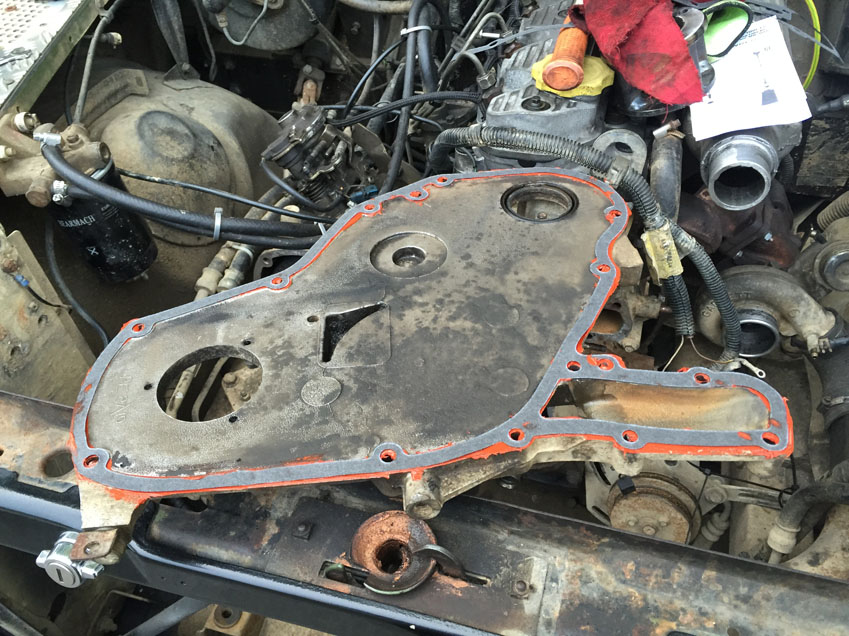
Refit the front cover with the correct bolts in the correct places.
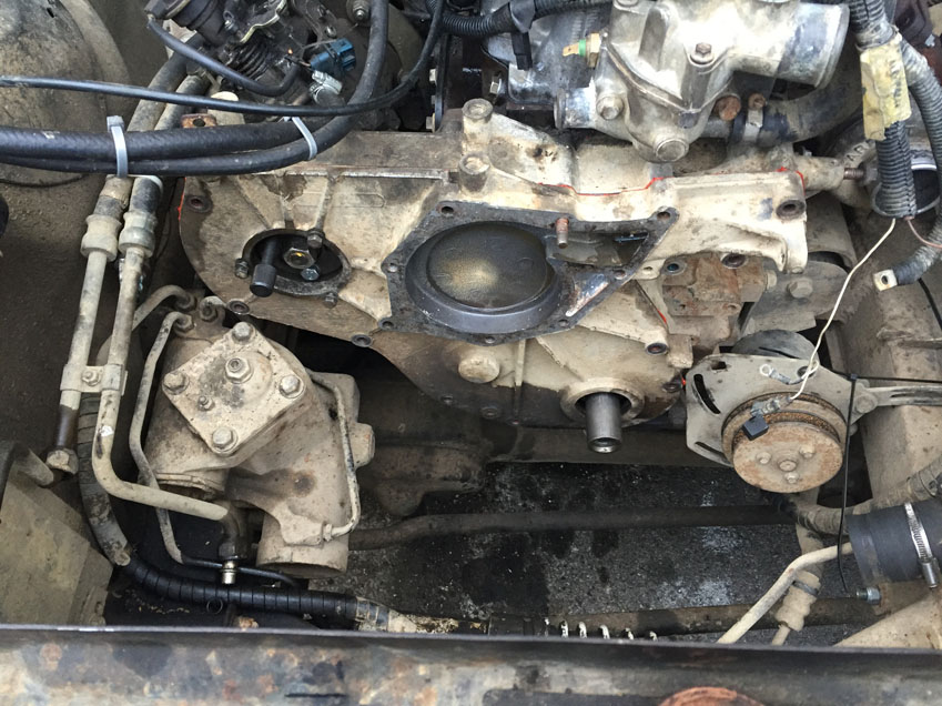
(it was starting to get dark at this point so the photo quality and number dwindled, but the refit is the reverse of the above and is fairly self explanatory)
Refit the water pump using a new gasket
Refit the Alternator and Power Steering pump along with their mounting bracket….fit the V belt and tension correctly
Apply some shaft locker fluid to the crankshaft and using a new bolt with loctite applied, fit the crank damper
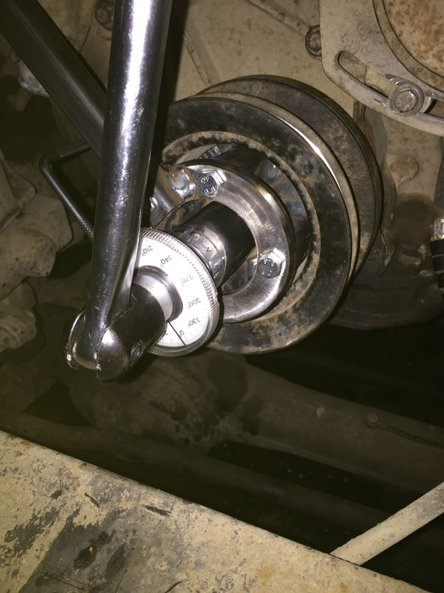
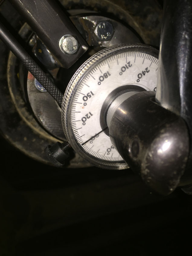
Remove all the timing pins and using the crank holding tool do up the crank bolt, then torque to 80Nm….now the fun begins, fit angular tightening gauge and breaker bar and heave like mad to turn a further 90deg.
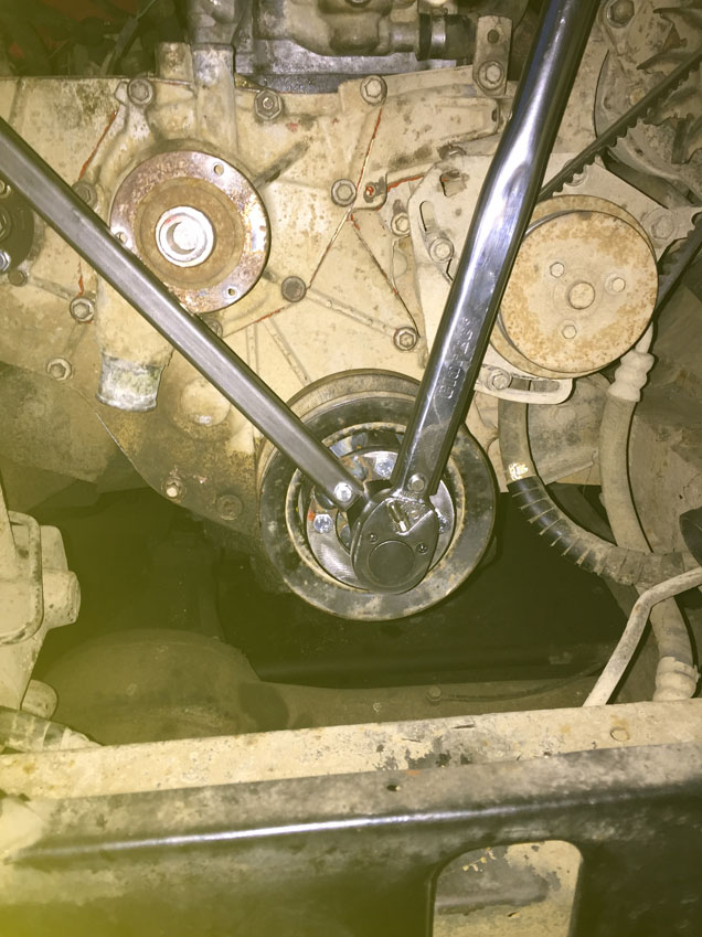
Take a 5 minute break and get your breath back, then fit the crank pulley, water pump pulley and V belt to the water pump then tension the belt by using a 1/2" drive extension and ratchet in the power steering pump bracket and applying tension the belt, do up the PS pump adjustment bolts and the pivot bolt.
(getting really dark now)
Refit the intake ducting the turbo
Refit the radiator, intercooler etc and pipe up correctly and refit the oil cooler unions. Replace the fuel pump pulley inspection port cover.
NOW…if you are only doing the timing belt…refill the coolant and bleed through as the rest of the engine should still be in one piece…check oil levels and your done.
If your head is still off for refurb…continue onwards….
Right…where were we with the head?? Oh yes, just got it off and replaced the cam followers…
As I had snapped the exhaust to turbo manifold studs, I had to sort this out.
Out with the welder (at work – easier) and welded some nuts to the studs and wound them out, refitted manifold to turbo using new bolts and copperslip grease.
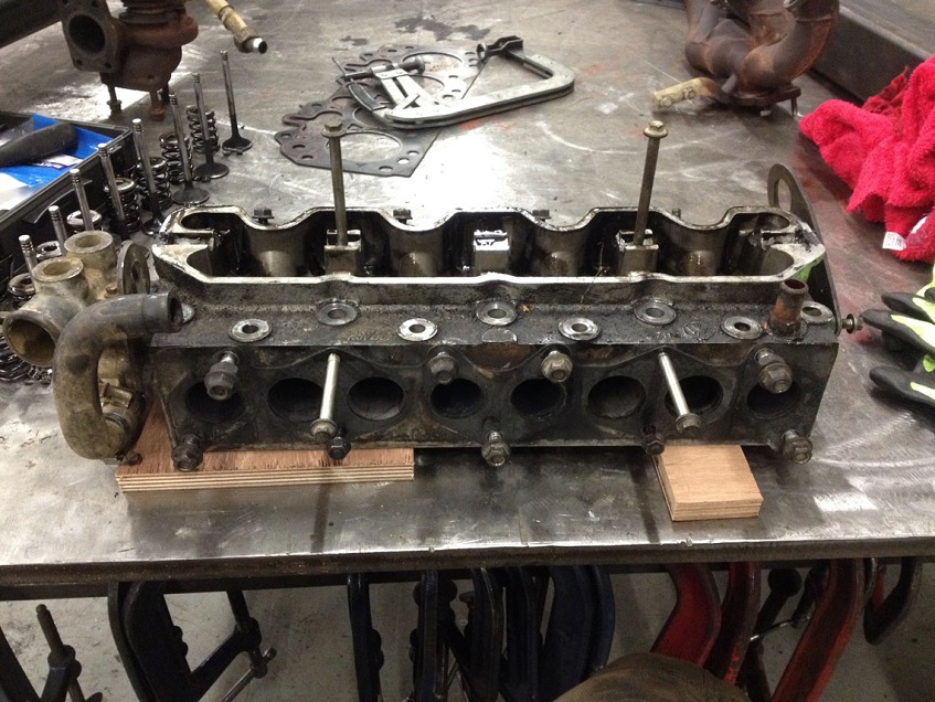
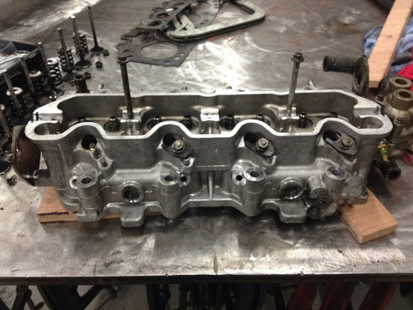
With the head on the work bench, remove the old gaskets and clean the mating faces
Using a OHV valve spring compressor, compress the spring and using a magnetic screwdriver or similar, remove the collets
Remove the spring and valve
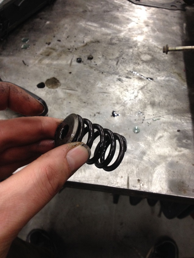
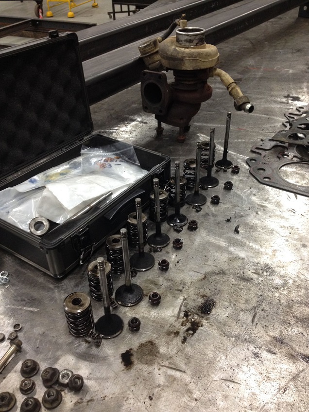
If you are refitting the same valves and etc, keep the valve, spring, collar, collets and spring seat all together in the correct group
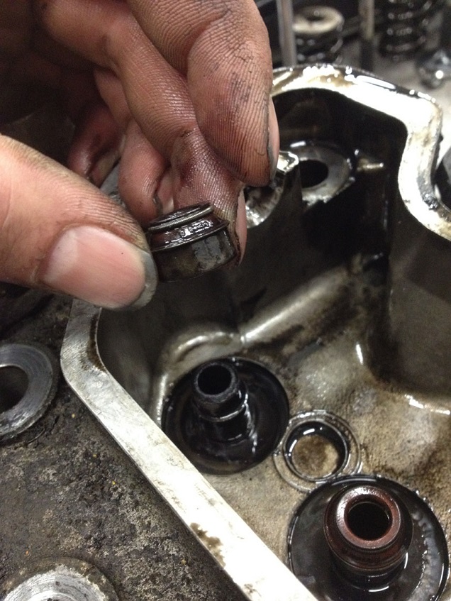
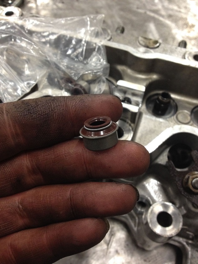
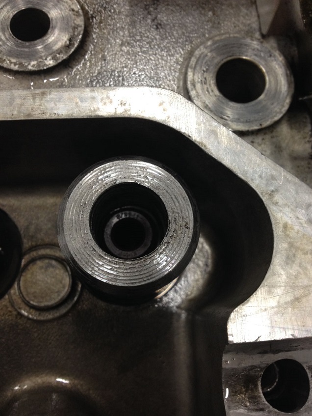
Place the head on some wood to protect the delicate mating face and pull off the valve stem seals
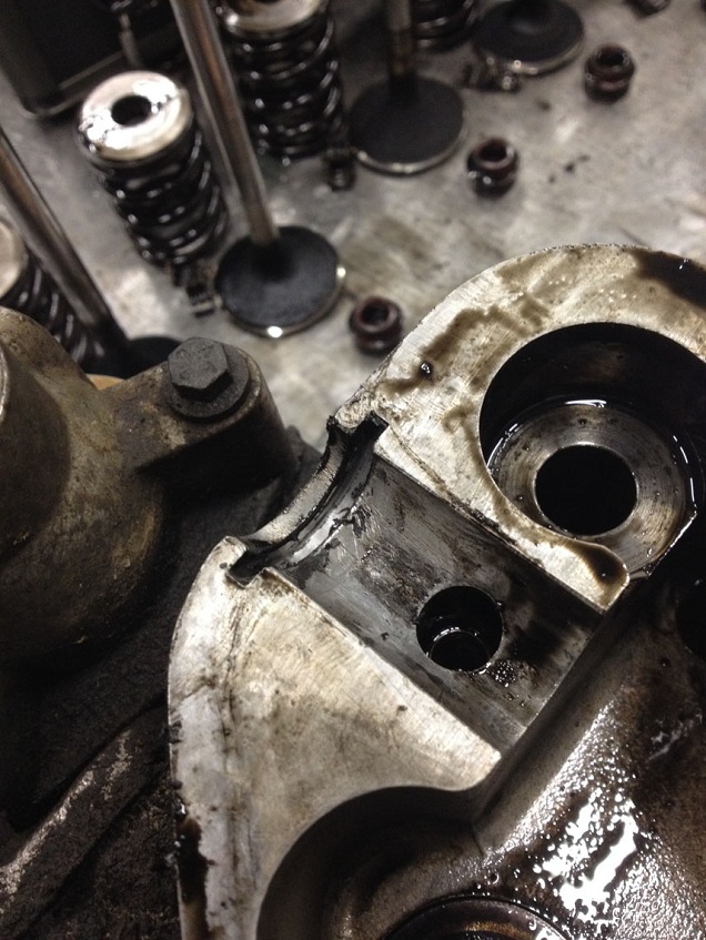
Remove the half-moon rocker cover seals
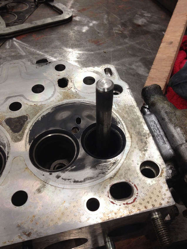
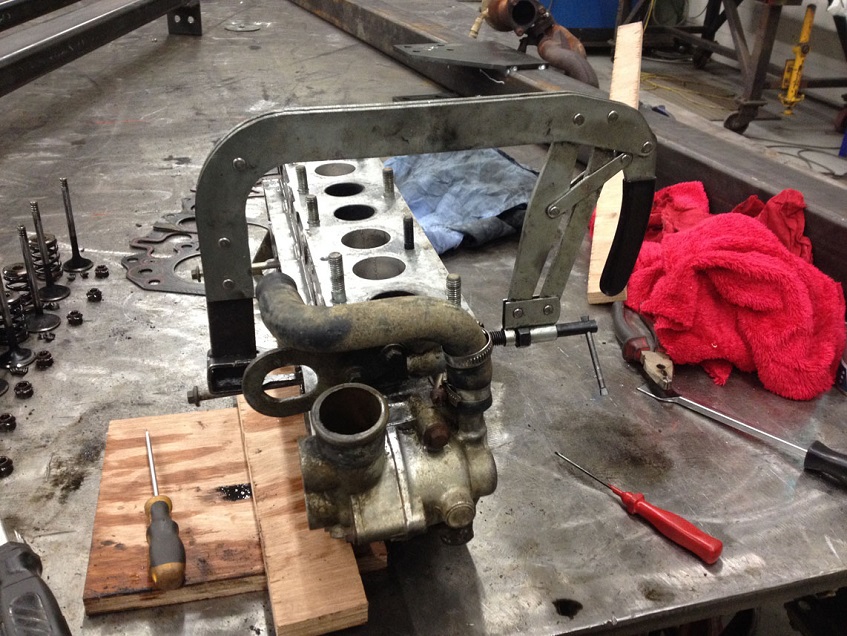
Using the LRT-12-036 tool (or the one you made yourself earlier like I did ) turn the head over and place on wooden blocks to lift the head up off the bench, drift out the old guides.
Now the fun part, luckily I was at work so no issues, but if you are at home, get permission from the other half and open the kitchen windows!
I used the spirit parts washer to degrease the head as best as possible and used the small Beling electric oven we use for heating up hydraulic jack seals for Aircraft Jacks to heat the head up to 120degC….if you are at home, this could pong a bit…hence why asking for permission from the other half and opening the windows is advised!
While the head is hot (wear gloves!) you can now drift in the new guides using LRT-12-045 and the LRT-12-515 spacer to get the right depth.
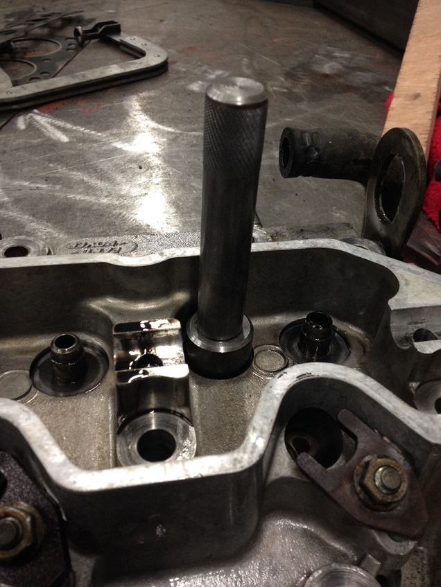
Try getting them all in, in one shot, else you’ll have to warm the head again once it has cooled a bit to get the rest in!
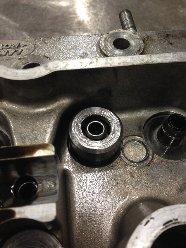
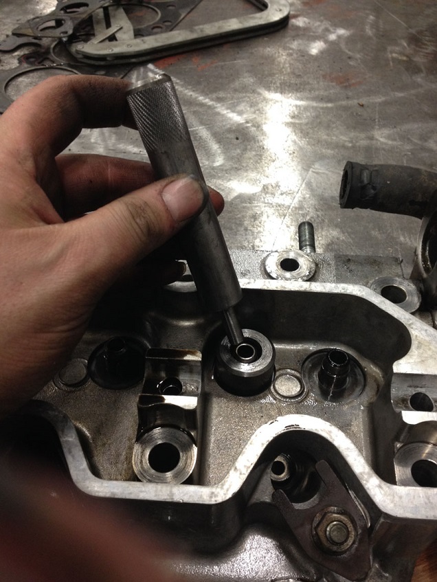
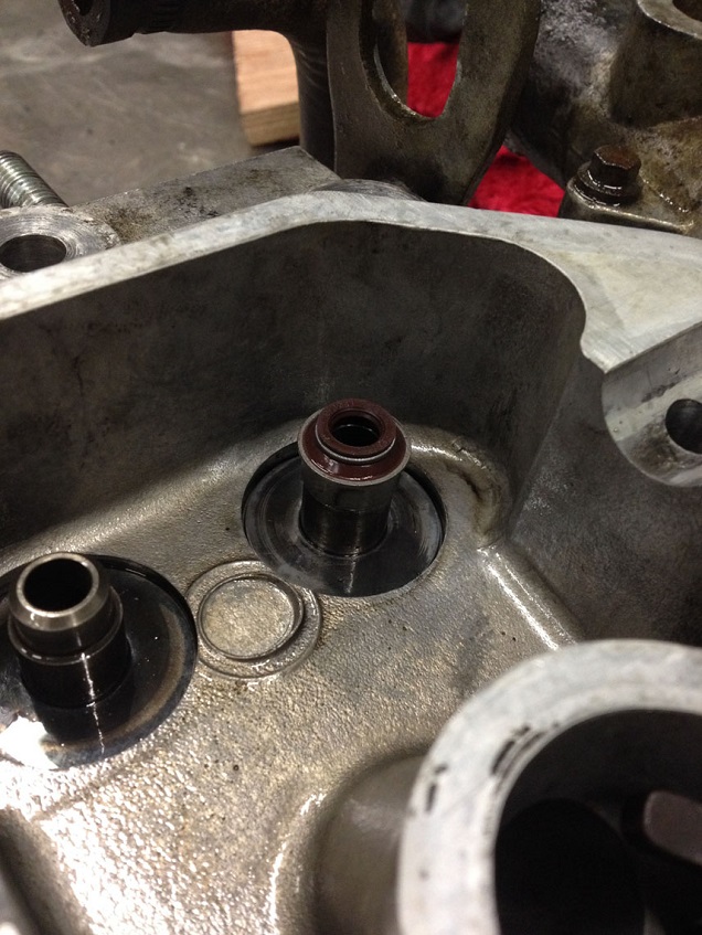
Once cooled for a while, fit new stem seals. I used the LRT-12-515 spacer I made as a dolly to push the seals squarely in place. First put the spring seat washer back on, then press the seal onto the guide
All fitted
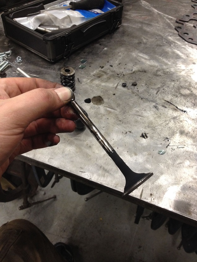
If fitting new valves, follow RAVE to lap in and seat the new valves correctly.
I refitted the original valves as they were not worn, pitted or defective in anyway (thankfully)
So, fit valve, spring, collar and compress with the spring compressor. Using a splodge of grease on the collet to make it stick to the valve stem, refit them and slowly uncompress the spring. Repeat another 7 times!
Once all done, place the head the right way up on some wood again, then a sharp tap (not a whack!!) on to the top of the valve stem to ensure the collets are seated correctly.
Head is ready for refit!
Clean the block mating face and fit the correct thickness gasket in the right orientation – See RAVE for information, but if you remove a 2 hole, replace with a 2 hole. If you can’t get the same hole gasket, get the next size up…never fit a thinner gasket! If in doubt fit a 3 hole or zero hole (zero is the thickest).
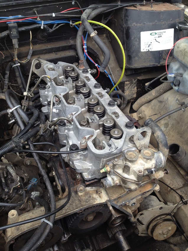
Carefully lower the head into position and locate on the dowels correctly (remembering to remove any rags from the bores!)
Head bolts can be reused up to 5 times according to RAVE, but not knowing the history of the engine, I replaced with new…cheap enough to do, full set for under £20 I think they were.
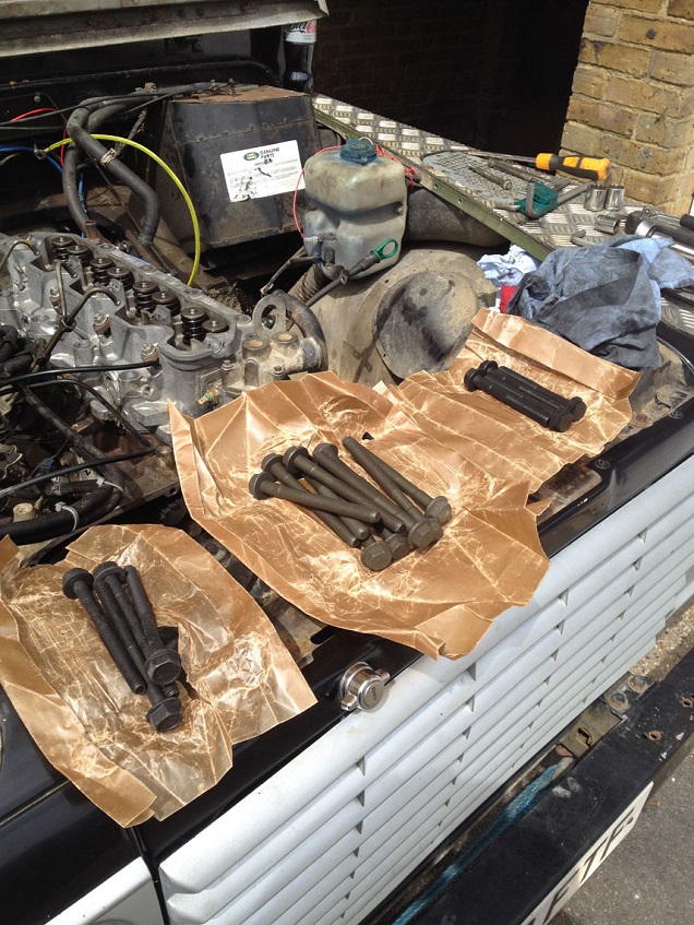
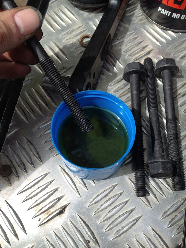
Lightly oil the threads with clean engine oil before placing them in the correct places (3 different bolts – so check RAVE for correct positions) DO NOT DROP the bolts into the holes – PLACE THEM.
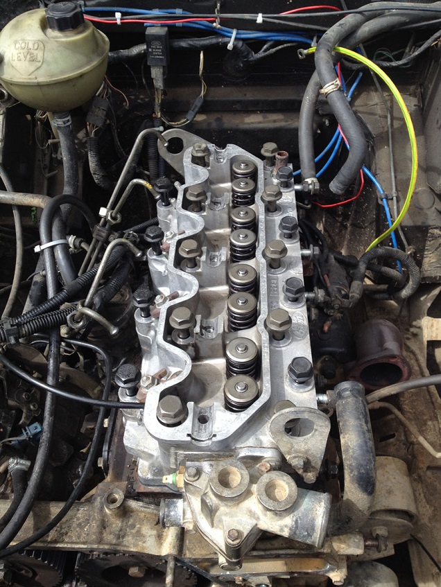
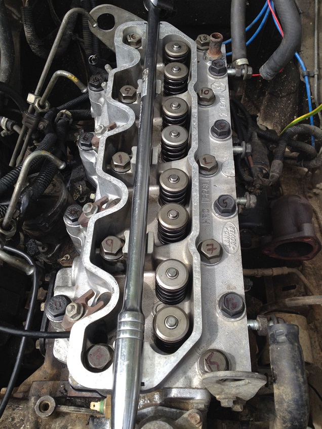
I numbered the bolts with a marker pen in the order they need to be torque and tightened (some photos show no numbers, cos I only thought to number them halfway through the sequence cos I kept getting lost)
First is to do them up finger tight till the heads meet the cylinder head surface, then do a first tighten in sequence to 40Nm.
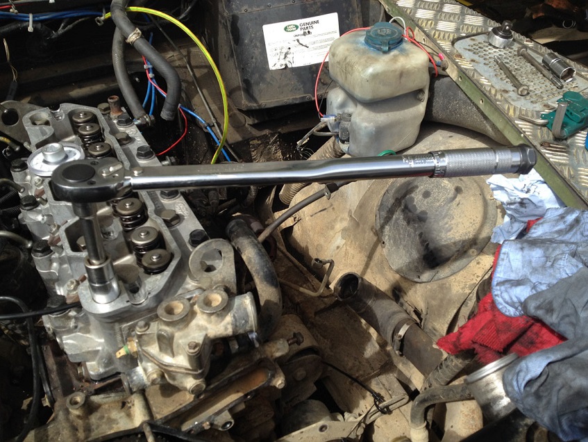
Then all bolts in sequence turned another 60deg angle
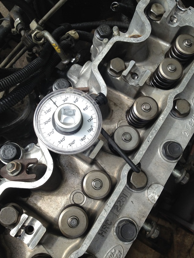
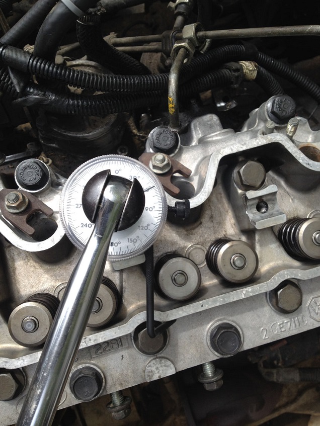
Then start from bolt number one and turn a further 60deg angle, (DO NOT turn all bolts to 120deg angle in one go, it must be done in stages)
And finally only bolts numbered 1,2,7,8,9,10,15,16,17 and 18 are to be turned a further 20deg angle. See RAVE for details and bolt numbers.
Fit a new inlet/exhaust manifold gasket.
Fit the exhaust manifold and turbo back on using copper grease on the studs
Refit the oil hose from the turbo to the block and the oil supply banjo to the top of the turbo
Rebolt the exhaust manifold bracket to the block (no photo sorry)
Refit the intake manifold and coolant pipe
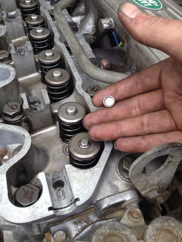
Fit new valve caps to the top of the valve stems
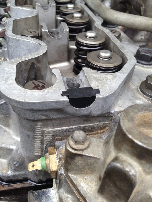
New half moon seals to the ends and refit the pushrods back into the correct position
Carefully refit the rockers and shaft and progressively torque down the shaft correctly as per figures in RAVE
Reset the valve clearances to 0.2mm as per RAVE sequence.
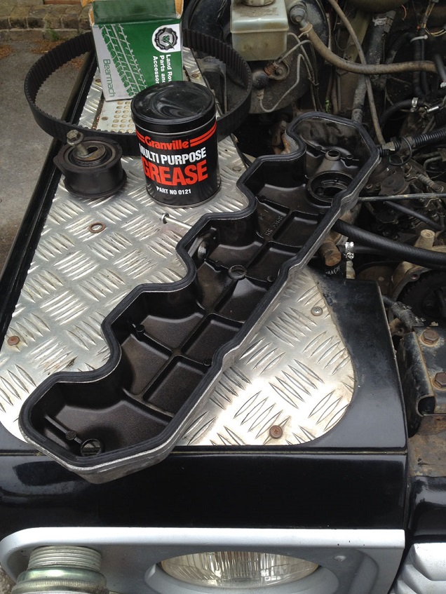
Fit a new seal to the rocker cover and fit cover in place
Clean the injectors using a degreaser, then smear with a thin layer of grease and fit a new sealing washer. Slip into the correct position and fit the clamp and nut. Note, the clamp is curved and should be installed with the curve uppermost, torque to the correct values as per RAVE (25-28Nm I think…but check first).
Refit the fuel unions and torque up, then fit new spill pipes and refit the glow plugs (torque correctly again!) I used some copperslip on the glow plugs to ease removal if necessary.
Fit the oil separator back to the rocker cover and ensure all the pipes are refitted correctly.
Double double check all connections are correct and present, the refill and bleed the coolant, check the engine oil, I flushed mine due to the damaged woodruff keys I found, and prime the fuel system using the manual lever on the lift pump (follow RAVE)
Then double check everything again and fire her up…might be a tad smelly as the new bits burn off any dust, transit grease, labels etc…but fingers crossed all is well.
NOTE: I know this How To, might be a bit disjointed in places, but I carried this out over a few days, and when I hit an obstacle, I changed onto sorting another part out while I waited for parts to arrive or I had to make a tool etc…so hence why some places it may seem a little rambling, but it should all be there in some order that can be followed if you are able to maybe scroll up and down a tad to line things up!
I will detail the tools dims shortly by editing this post this evening when I get home, as the dims are there!
This How To is for the changing of the 200TDi (Disco engine in a Ninety) Timing Belt, Cylinder Head gasket, Cam Followers and Guides, Cylinder Head Valve Guides and Seals, Water Pump Gasket, and chaning of the Cranks Shaft Timing Gear and the Belt Tensioner. (was fun!)
I will also detail down the special tools I made for the crankshaft pulley holding, valve guide drifts and spacer etc.
Tools required:
• Good selection of Spanners and Sockets, mainly 8, 10, 13, 14, 15, 17 (can’t remember at the moment but sure I used it), 19 (head bolts), 24 (pump pulley), 28 spanner (turbo oil line to block), 30 (crank damper) and 7/8” spanner (oil cooler)
• Viscous fan spanner is handy
• Diesel Fuel Pump Timing Kit – similar to http://www.ebay.co.uk/itm/Pro-Land-...395?pt=LH_DefaultDomain_3&hash=item46316be18b and the good thing is the large round pulley holder is also used for pulling the crank damper off!! Brilliant for the price of about £25
• Diesel Injector Puller – similar to http://www.ebay.co.uk/itm/Professio...254?pt=LH_DefaultDomain_3&hash=item3f2ae9dd46
• Crank Holding Tool, I made mine details attached
• Valve Guide Drifts LRT-12-046, LRT-12-036 and Spacer LRT-12-515…..I made mine using a lathe at work, I took the dims available from a well known tooling website and scaled the photos using AutoCAD and guesstimated the unknown dims and made the tools using some scrap material we had. Details and Dims also attached if you fancy having a go.
• All important torque wrenches and angular tightening gauge
• Dial gauge/Torsion Bar torque wrench for timing belt tensioning
Prep work:
Soak manifold bolts and turbo manifold bolts plus any other stubborn looking bolts in a penetrating fluid. Clean the areas around the injectors, glow plugs flywheel housing drain plug to prevent dirt ingress. If you are to remove the glow plugs, get the engine up to temp and loosen the plugs first, then leave over night for it to cool before starting this work.
To task:
Rember I am doing both head and timing chain, so some tasks are not required for just timing cover and vice versa, I’ll let you make your judgement on which parts to follow to achieve your result.
First off, remove the viscous fan. This is a left hand thread and if you are lucky it will knock off with ease. If not, place a spanner on one of the water pump pulley bolts and rotate until the spanner shaft butts up against the pump spindle and hold this spanner to retain the water pump from turning and undo the fan nut.
Remove radiator top hose and top intercooler hose
Undo the top two nuts holding the rad cowling in place and with a wiggle withdraw
Remove the pump to stat hose and the rad bottom hose from the water pump
Get yer timing kit out
Turn the Crank to TDC as marked on the pulley and check you can correctly fit the flywheel timing pin, a wiggle with a flat screw driver may be required to line up the flywheel just-so.
Undo the Fuel Pump pulley inspection port and wiggle the fuel pump timing pin in place, this has now set the engine in time correctly, if the fuel pump pin is tight fit, slacken the pulley adjustment bolts and using a socket and handle, turn the fuel pump a smidge until you can get the pin to fit correctly.
With tension on the V belts, loosen the water pump pulley bolts. Then loosen the power steering pump adjustment bolts and pivot bolt and loosen the V belt and remove along with the water pump pulley.
Using the Crank holding tool, sweat and bleed to undo the crank bolt…mine was looser than expected!
Fit the damper pulling tool from the timing kit and draw off the damper from the crank.
Undo the bolts surrounding the water pump and remove. Not necessary to remove the pump if you are only renewing the belt or the head etc, I removed so I could check the gasket seal. But a couple of the bolts do go through the water pump into the block so will need to be removed in order to remove the timing belt cover.
Loosen the Alternator adjustment bolts and the pivot bolt to reduce tension on the V belt, and remove belt.
DISCONNECT THE BATTERY. Taking note of the wiring position on the Alternator (this is mine but check yours, Land Rovers have been known to be different from eachother!)
And remove the Alternator. As I was taking the head off, I took this opportunity to also remove the turbo to intercooler hose at this point.
Remove the power steering pump from the bracket
Remove the bracket (2 bolts, 2 nuts)
Undo the remaining bolts on the front cover and note there positions….I didn’t and it then took me a while to get the right length bolts back in the right holes again!
Think I have found the reason the pistons and valves met and snapped the pushrod!
If you are only doing the belt…then this is as much stripping you need to do to access the belt….carry on further down to show the belt change process and retiming and refitting etc….
I did the head too, so below is the remainder of bits and bobs to do to remove and refurb the head.
Undo the 2 long bolts and the 2 nuts and remove the intake manifold.
Remove the coolant rail.
Now you have a few choices….I removed the whole turbo and exhaust manifold, but you can just either undo the manifold bolts and lever the manifold away from the head and leave in place, or remove the manifold from the turbo and the head…this is what I started to do, but the manifold to turbo studs sheared, and one I could not get off for love nor money…..so I removed the turbo along with the manifold. This involved removing the oil supply banjo to the top of the turbo and the oil return to the block and the manifold support bracket to the block.
I would advocate if possible to remove the manifold from the turbo and the head, as levering it away from the head it may get in the way, but it is your choice.
Remove the oil separator from the rocker cover and remove the cover.
Progressively slacken the rocker shaft bolts and remove the shaft, be careful to not remove the bolts fully from the shaft as they retain the shaft retaining caps, springs, washers etc in place, so just undo them but not remove the bolts, then lift the shaft off the head with the bolts still in the shaft.
Using a piece of card numbered, pull the pushrods out and keep in order, as you’ll see No.8 on mine is missing as it had snapped.
Remove the leak off pipes linking the injectors
Remove the glow plugs by first removing the electrical cable to them and carefully unscrewing from the head, they can be stubborn depending on how long they have been in there….I would advocate that BEFORE doing any of this work, run the engine up to temp and shut off, then loosen the glow plugs. Then leave too cool before starting this work, as a hot engine makes it easier at times to remove stuck glow plugs.
Undo the fuel unions to the top of the injectors, RAVE says to completely remove the pipes, but this is not strictly necessary.
Loosen the fuel injector clamp nuts and clamps then using an injector puller (slide hammer thingy) pop the injectors out. Place in a clean dry place, in the order they were removed.
Head is now ready to be unbolted. Using the CORRECT sequence, crack off each bolt in turn, then progressively undo in sequence to prevent warping the head.
With a tiny tap to break the gasket seal (the head is located on dowels so don’t whack it sideways to much) the head should be able to be lifted off carefully.
Witness marks on the piston crowns and the underside of the valves show where the valves and pistons had met, luckily they only just met and no valves were bent and the piston crowns not dented or split! (ignore the minor water spilt from the head when I removed it) Also I was pleased to see the honing marks still visible on the bores, so the engine has been looked after in is life!
So with the head off and placed safely to one side (never rest the head on the floor with the mating side downwards else irreversible damage can be made to the valves, mating face and etc) the cam followers, slides and guides can be renewed.
Undo the bolt on the side of the block until the little spigot is just inside the guide to prevent the guide slipping down to far, but allows the slide to be withdrawn. I used a small allen key to hook the slide and lift out, sometimes the roller follower will be attached to the slide via oil ‘suction’ and other times it will fall of the slide back to the cam (hence why the guide MUST remain in place until the slide and roller have been removed). Once the slide is removed, a long nose pair of pliers can be used to carefully withdraw the roller.
Once they are out, the guide can be removed by retaining with yer finger and removing the bolt on the side fully.
Replace with new in the reverse fashion, guide first then roller and the slide (note the slides have an F on front face….replace with this F facing the front of the engine)
One bolt is in a silly place, so you’ll need to remove the socket cap to withdraw the bolt
Cover the open bores and piston crowns with rags stuffed in the open holes, and I place a piece of wood over the top of the block so no damage can be made to the mating surfaces while I did the rest of the work.
So, if you are just doing the timing belt…carry on from here! Head refurb will follow the belt replacement instructions!
Remove the tensioner
The belt can now be removed (you must make sure the timing pins are installed and remain installed while the belt is off.)
If you are replacing the idler, you can now remove that too.
Found the reason my cam and pump timing was out….
If you have been following my other threads, you not this was a bit of a mystery, until I removed the sprocket and found the horror.
In order for me to remove the sprocket as mine was fubar’d I needed to remove the rad, intercooler and oil cooler….
No photos of this, sorry, but it is basically, remove the oil unions to the side of the rad and catch any spilt oil, remove the lower intercooler hose, top and bottom hoses were already undone. Undo the 4 bolts holding the retaining plates to the slam panel and then lift the whole rad/intercooler assembly out in one lump
Using a makeshift puller from the timing kit and some M5 studding, pull the sprocket off the crankshaft.
To discover my horror underneath!
Knock the woodruff keys out (replace them anyway even if yours look fine)
Check the sprocket for wear and replace as I had too..!!
NOTE the depth of seal engagement into the rear of the timing case and then remove the crankshaft seal using a seal puller or a large flat screwdriver
Using some wet/dry paper and some lube (I used WD40) clean the crankshaft end
Grease up a new crank seal and fit in place, I used a length of tube of suitable diameter to seat the seal in the correct depth, but very careful drifting with a block wood will do the job, just try to keep it square as it goes in.
Replace the woodruff keys and slide the crank timing sprocket in to place and drift in to position
Fit the new idler, realign the Camshaft pulley gear correctly and thread the belt into position keeping tension on the belt as it comes off the crank sprocket, round the idler, over the cam sprocket….when you get to the fuel pump pulley (the locking pin should still be engaged), ensure it is loose and turned to roughly halfway of its travel, then thread the belt tightly over the top of the pulley allowing the pulley to rotate slightly so the teeth and belt align.
Then fit the tensioner into position, but refrain from doing up the bolt fully.
Now you must use a dial gauge/torsion bar style torque wrench to set the tension on the belt, a clicky torque wrench will not do the tension correctly.
I got mine from Halfords, made by Parker Tools and cost about £40….the downer is, it comes with a 3/8” drive and the tensioner is a 1/2" square hole!
Not having time to go back to work to make a proper adaptor, I hammered an 8mm 3/8” drive socket into the end of a 1/2" drive extension, then ground the end of the extension to a flatter finish as the rounded end kept jumping out of the locating hole.
Apply tension to the belt to a reading of approx 18Nm (for a new belt) and tighten the tensioner bolt. Check RAVE for tension.
Install the crank bolt, and do up the fuel pump pulley adjuster bolts.
Remove the fly wheel timing pin and the fuel pump timing pin and rotate the crank CLOCKWISE TWICE, and return to TDC
Refit the timing pins, and loosen the fuel pump pulley adjuster bolts again, loosen the tensioner, and retension the belt using the above method again, and tighten the tensioner bolt. The belt tension is now set correctly.
Remove the crankshaft bolt and do up the fuel pump adjuster bolts correctly.
Technically the timing pins can now be removed, I left them in until it was time to do up the crank bolt fully, but that was my choice.
Clean up the front cover and fit a new gasket and crank seal, I used some gasket sealant to hold the paper gasket in place as it kept moving.
Refit the front cover with the correct bolts in the correct places.
(it was starting to get dark at this point so the photo quality and number dwindled, but the refit is the reverse of the above and is fairly self explanatory)
Refit the water pump using a new gasket
Refit the Alternator and Power Steering pump along with their mounting bracket….fit the V belt and tension correctly
Apply some shaft locker fluid to the crankshaft and using a new bolt with loctite applied, fit the crank damper
Remove all the timing pins and using the crank holding tool do up the crank bolt, then torque to 80Nm….now the fun begins, fit angular tightening gauge and breaker bar and heave like mad to turn a further 90deg.
Take a 5 minute break and get your breath back, then fit the crank pulley, water pump pulley and V belt to the water pump then tension the belt by using a 1/2" drive extension and ratchet in the power steering pump bracket and applying tension the belt, do up the PS pump adjustment bolts and the pivot bolt.
(getting really dark now)
Refit the intake ducting the turbo
Refit the radiator, intercooler etc and pipe up correctly and refit the oil cooler unions. Replace the fuel pump pulley inspection port cover.
NOW…if you are only doing the timing belt…refill the coolant and bleed through as the rest of the engine should still be in one piece…check oil levels and your done.
If your head is still off for refurb…continue onwards….
Right…where were we with the head?? Oh yes, just got it off and replaced the cam followers…
As I had snapped the exhaust to turbo manifold studs, I had to sort this out.
Out with the welder (at work – easier) and welded some nuts to the studs and wound them out, refitted manifold to turbo using new bolts and copperslip grease.
With the head on the work bench, remove the old gaskets and clean the mating faces
Using a OHV valve spring compressor, compress the spring and using a magnetic screwdriver or similar, remove the collets
Remove the spring and valve
If you are refitting the same valves and etc, keep the valve, spring, collar, collets and spring seat all together in the correct group
Place the head on some wood to protect the delicate mating face and pull off the valve stem seals
Remove the half-moon rocker cover seals
Using the LRT-12-036 tool (or the one you made yourself earlier like I did
) turn the head over and place on wooden blocks to lift the head up off the bench, drift out the old guides.
Now the fun part, luckily I was at work so no issues, but if you are at home, get permission from the other half and open the kitchen windows!
I used the spirit parts washer to degrease the head as best as possible and used the small Beling electric oven we use for heating up hydraulic jack seals for Aircraft Jacks to heat the head up to 120degC….if you are at home, this could pong a bit…hence why asking for permission from the other half and opening the windows is advised!
While the head is hot (wear gloves!) you can now drift in the new guides using LRT-12-045 and the LRT-12-515 spacer to get the right depth.
Try getting them all in, in one shot, else you’ll have to warm the head again once it has cooled a bit to get the rest in!
Once cooled for a while, fit new stem seals. I used the LRT-12-515 spacer I made as a dolly to push the seals squarely in place. First put the spring seat washer back on, then press the seal onto the guide
All fitted
If fitting new valves, follow RAVE to lap in and seat the new valves correctly.
I refitted the original valves as they were not worn, pitted or defective in anyway (thankfully)
So, fit valve, spring, collar and compress with the spring compressor. Using a splodge of grease on the collet to make it stick to the valve stem, refit them and slowly uncompress the spring. Repeat another 7 times!
Once all done, place the head the right way up on some wood again, then a sharp tap (not a whack!!) on to the top of the valve stem to ensure the collets are seated correctly.
Head is ready for refit!
Clean the block mating face and fit the correct thickness gasket in the right orientation – See RAVE for information, but if you remove a 2 hole, replace with a 2 hole. If you can’t get the same hole gasket, get the next size up…never fit a thinner gasket! If in doubt fit a 3 hole or zero hole (zero is the thickest).
Carefully lower the head into position and locate on the dowels correctly (remembering to remove any rags from the bores!)
Head bolts can be reused up to 5 times according to RAVE, but not knowing the history of the engine, I replaced with new…cheap enough to do, full set for under £20 I think they were.
Lightly oil the threads with clean engine oil before placing them in the correct places (3 different bolts – so check RAVE for correct positions) DO NOT DROP the bolts into the holes – PLACE THEM.
I numbered the bolts with a marker pen in the order they need to be torque and tightened (some photos show no numbers, cos I only thought to number them halfway through the sequence cos I kept getting lost)
First is to do them up finger tight till the heads meet the cylinder head surface, then do a first tighten in sequence to 40Nm.
Then all bolts in sequence turned another 60deg angle
Then start from bolt number one and turn a further 60deg angle, (DO NOT turn all bolts to 120deg angle in one go, it must be done in stages)
And finally only bolts numbered 1,2,7,8,9,10,15,16,17 and 18 are to be turned a further 20deg angle. See RAVE for details and bolt numbers.
Fit a new inlet/exhaust manifold gasket.
Fit the exhaust manifold and turbo back on using copper grease on the studs
Refit the oil hose from the turbo to the block and the oil supply banjo to the top of the turbo
Rebolt the exhaust manifold bracket to the block (no photo sorry)
Refit the intake manifold and coolant pipe
Fit new valve caps to the top of the valve stems
New half moon seals to the ends and refit the pushrods back into the correct position
Carefully refit the rockers and shaft and progressively torque down the shaft correctly as per figures in RAVE
Reset the valve clearances to 0.2mm as per RAVE sequence.
Fit a new seal to the rocker cover and fit cover in place
Clean the injectors using a degreaser, then smear with a thin layer of grease and fit a new sealing washer. Slip into the correct position and fit the clamp and nut. Note, the clamp is curved and should be installed with the curve uppermost, torque to the correct values as per RAVE (25-28Nm I think…but check first).
Refit the fuel unions and torque up, then fit new spill pipes and refit the glow plugs (torque correctly again!) I used some copperslip on the glow plugs to ease removal if necessary.
Fit the oil separator back to the rocker cover and ensure all the pipes are refitted correctly.
Double double check all connections are correct and present, the refill and bleed the coolant, check the engine oil, I flushed mine due to the damaged woodruff keys I found, and prime the fuel system using the manual lever on the lift pump (follow RAVE)
Then double check everything again and fire her up…might be a tad smelly as the new bits burn off any dust, transit grease, labels etc…but fingers crossed all is well.
NOTE: I know this How To, might be a bit disjointed in places, but I carried this out over a few days, and when I hit an obstacle, I changed onto sorting another part out while I waited for parts to arrive or I had to make a tool etc…so hence why some places it may seem a little rambling, but it should all be there in some order that can be followed if you are able to maybe scroll up and down a tad to line things up!
I will detail the tools dims shortly by editing this post this evening when I get home, as the dims are there!
Last edited: