cracked chassis repair- no welding

This site contains affiliate links for which LandyZone may be compensated if you make a purchase.

john t

Active Member
Posts
680
Location
basingstoke
i have had the cracked chassis noise for a few months and as the noise was getting worse i thought it was about time i tackled the issue, its a very common problem on the freelander,
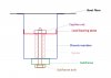
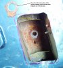
usually on the off side, its where the rear subframe - front bolt is attached to the chassis,
what happens is the welded spacer that goes through the chassis, becomes detached, causing a creaking noise usually when reversing.

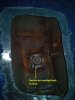
my fix dose not require any welding and takes less than an hour, all that is required is a steel plate approx 8mm x50mm x150mm, with a hole drilled in the centre.
1, remove the offside rear wheel and place chassis securely on axelstand
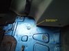
2, from the inside pull back the carpet, to reveal the chassis retaining bolt access point, remove the cap and inspect the nut, you may see signs of movement ,
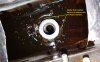
3, mark out and cut an access hole around the access point within the chassis , the larger the better.
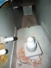
4 remove the bolt, the nut is captive but will most probably rotate,also remove the nut and with a bit of persuasion remove the spacer ,it might require a small chisel or breaking out with a drill, mine came out freely as the weld was completely broken.
5,put the spacer in a vice and cut off approx 5mm
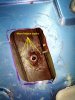
6, reassemble in reverse order and fitting the prepared steel plate, tighten the bolt ensuring the whole assembly is tight.

job done ,no more creaking
 
Hi john t

thats interesting

I too get a funny creaking, graunching noise when reversing and a little bit when going forwards under certain conditions
Mines a left hand drive though - is it still the right hand side of the car that tends to break ??
do you have any photos of your job by any chance ??

thanks

Digby
 
Just resurrecting this thread, as I've just fixed mine this weekend, and took some photos, which might be helpful to anyone doing the job in the future. My fix does, however, involve welding...

...lots of welding...

On a positive note, the job can be done with the car on the ground. No jacking up required. However, it's still quite involved! Landrover's original design was poor. The loads transmitted along the bolt are fed into the middle of flat skins, which just "pant" up and down as the load comes on and off, ultimately, fatiguing the chassis. Although I can't be certain, it looks like the only thing Landrover actually welded, was the captive nut. That sits on a plate inside the chassis box section, about half way up its height. This makes a good repair very difficult. Looking online, I've seen people drop the subframe and weld a plate on the bottom of the chassis. I didn't want to do that, as I thought it would space one corner of the subframe down slightly. Also, it only feeds the load into the bottom skin of the chassis member because the plate to which the captive nut mounts, will probably have fatigued anyway by the time you're doing the job.
Schematic.jpg

I started by lifting the boot carpet. Fortunately, there's a blanking cap in the boot floor, directly above the captive nut in question.
IMG_20190608_152621.jpg

Levering the blanking plug out, gave me a convenient hole to poke a jigsaw through to cut an access hole.
IMG_20190608_154415a.jpg

It was pretty easy to spot the fatigue cracks!
IMG_20190608_154440.jpg


Incidentally, it's a good idea to use a vacuum cleaner to get as much of the swarf out as possible because otherwise, it'll start to rust and eat through the coating on the chassis, accelerating rusting from the inside. Once I'd cut the captive nut off, there were more cracks...

IMG_20190608_160259a.jpg


I then cut through the load bearing plate that's spot-welded half way down the depth of the chassis box section and removed the cylindrical spacer bush. As far as I could tell, this wasn't welded to the bottom skin of the chassis, it's just there to stop the two skins pulling together when the bolt is tightened. Once it was out of the way, I could see that it had fatigues a neat hole, the same diameter as itself, through the bottom skin of the chassis. The positioning dowel on the subframe doesn't help either!

IMG_20190608_162336a.jpg


I cleaned up the loose pieve and the surrounding metal (which is quite hard to do because they're deep down). An air file helped!

IMG_20190608_165422a.jpg


I then welded it back in, REALLY CAREFULLY. I didn't want to melt through it and weld the bottom of the chassis to the subframe! Those welds don't have to be strong. Just tacks to hold it in place. They then need to be ground off flush again afterwards so that the bush sits square on top of the weld - again, it's messy to get in there without a die grinder or air file. Unfortunately, I forgot to take a photo of that stage! I then cleaned up the outside of the bush and welded it to the bottom of the chassis as best I could. It's hard to get a welding torch down there, but any weld you can get will be better than what was there originally!

IMG_20190608_184611a.jpg


Unfortunately, I also forgot to photograph that bit but you can see the weld under the Dinitrol rust inhibitor (and yeah... that wasn't such a great idea because I then set it on fire a few times doing the next bit of welding)! After that, I cut another plate to replace the section of the load bearing plate I'd cut out. I put a hole in the top of it for the spacer bush to poke through, and chamfered the inside edge to get a good weld prep. The original load bearing plate is 2mm thick, so I went up to 2.5mm for the replacement.

IMG_20190608_184642a.jpg


I then welded it all round, doing short runs of weld and then leaving it to cool so it didn't build up too much heat. Not the prettiest but at least access for the torch is a bit better now that you're higher up the chassis box section.

IMG_20190608_194044a.jpg


And then I put the original captive nut over it and tightened the bolt through the subframe temporarily, so it was held in the right place whilst I welded the cage for the nut back on.

IMG_20190608_204249a.jpg


At least welding the cage to the plate still allows the captive nut to float slightly to help with alignment when fitting the bolt back in. The last stage was to weld a closing plate back on the boot floor. That's much thinner than the load bearing plate. I had some 0.9mm from an old filing cabinet which was just the job. Again, I forgot to take a photo of it welded, but that's the easy bit. Here it is with some epoxy on it.

IMG_20190608_234158a.jpg


If the car made it to 18 years old before I had to do this, I'm kind-of hoping I won't ever have to do this job again!
 

Attachments

  • Schematic.jpg
    Schematic.jpg
    48 KB · Views: 222
  • IMG_20190608_152621.jpg
    IMG_20190608_152621.jpg
    339.4 KB · Views: 367
  • IMG_20190608_154440.jpg
    IMG_20190608_154440.jpg
    554.1 KB · Views: 392
  • IMG_20190608_160259a.jpg
    IMG_20190608_160259a.jpg
    263.7 KB · Views: 300
  • IMG_20190608_162336a.jpg
    IMG_20190608_162336a.jpg
    500.3 KB · Views: 317
  • IMG_20190608_162336a.jpg
    IMG_20190608_162336a.jpg
    500.3 KB · Views: 223
  • IMG_20190608_162336a.jpg
    IMG_20190608_162336a.jpg
    500.3 KB · Views: 205
  • IMG_20190608_162336a.jpg
    IMG_20190608_162336a.jpg
    500.3 KB · Views: 215
  • IMG_20190608_184611a.jpg
    IMG_20190608_184611a.jpg
    298.3 KB · Views: 309
  • IMG_20190608_204249a.jpg
    IMG_20190608_204249a.jpg
    135.4 KB · Views: 270
Back
Top