- Posts
- 6,505
- Location
- North Perthshire

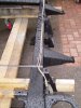
Alas no, it is the much-discounted original with allowances made for the attachment of a second set of hangers. The plan is to cut the ones off my existing chassis and weld them to the correct rails, that way I don't need to disturb the galv more than necessary.Is that the replacement chassis with correct exhaust hangers??
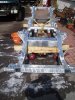
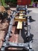
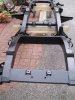
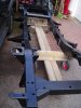
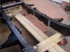
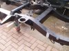
Alas no, it is the much-discounted original with allowances made for the attachment of a second set of hangers. The plan is to cut the ones off my existing chassis and weld them to the correct rails, that way I don't need to disturb the galv more than necessary.
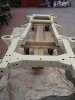
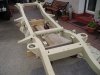
Yes!!!! Amazing things have happened - will catch up over the next few days. Suffice to say that the old chassis is no more....and the new is almost ready to receive the body back on.Any progress which the ole' beast?
Welcome To LandyZone, the Land Rover Forums!
Here at LandyZone we have plenty of very knowledgable members so if you have any questions about your Land Rover or just want to connect with other Landy owners, you're in the right place.
Registering is free and easy just click here, we hope to see you on the forums soon!