The dimmer that Lorri789 has pictured is on a Range Rover Classic, they were all fitted with them.
But, they were fitted in a vertical orientation, to the angled lower facia, so they won't fit into a D2, which has its dimmer mounted horizontally to the lower edge of the instrument binnacle.
On D2s, only the US and Japan got dash dimmers, so only they have the connector in the facia harness, UK models don't have it.
I have a few D2 dimmers, and can make the harness to connect into the D2's facia harness.
Here are the pictures and instructions that I did for a Swedish member on the D2BC, who has a LHD vehicle.
In the pictures, I'm using a RHD facia harness (and a LHD Dimmer Harness), I've 'flipped' the facia harness, so that it looks like a LHD one in the pictures.
The facia harness has also had some of it's binding tape removed, which is why it looks like a loose bundle of wires in places.
The connections for the RHD dimmer harness are the same but, on a LHD vehicle, the positions of
C0759 and
C0760 are reversed, so the harness in the pictures has longer lighting wires than the earth wire (on a RHD dimmer harness the earth wire is longer than the lighting wires).
In RAVE, Land Rover number a connector's cavities from left to right on the front (face) of the connector.
So, for clarity, I've modified a Grey Header diagram, to show the cavity numbers from the cable-entry side of the connector -
We'll start with
C0760
Pointing at cavity 12, which is one of 4 terminals on the LG sub-circuit (Instrument Pack Live) - we'll avoid connecting to this -
Pointing to cavity 3, where the dimmer's earth will be connected to -
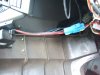
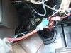
Next three pictures - Inserting the Dimmer Harness earth terminal (Black wire) into cavity 3, note the orientation of the terminal -
Now
C0759
Pointing to cavity 12 on the illumination feed circuit on Header
C0759, note the empty cavity 11 next to it, we'll be using that cavity soon -
Pointing to cavity 13 on the switch and instrument illumination circuits on Header
C0759 -
On non-dimmer vehicles, terminals 12 and 13 of are connected together by a loop of Red/Orange cable, this loop connects the illumination feed circuit (terminal 12) to the switch and instrument illumination circuits (terminal 13).
This loop also has a splice off of it, which powers the headlamp levelling circuit, via the headlamp levelling switch (more of this later)
On vehicles fitted with a Dash Dimmer, the dimmer's input and output go between terminals 11 (same sub-circuit as terminal 12) and terminal 13.
We will need to release the terminal in cavity 13 - lever the splice cap away from it's latches on the connector body -
With the side of the splice cap lifted above the latches, hold the connector body and pull the splice cap with a pair of pliers, it may help to wiggle it, or pull from each end alternately -
Done
From the front of the splice connector - pointing to the terminal in cavity 13 (you can see the plastic retainer below it) -
Next 2 pictures - Depressing the plastic retainer to release the terminal -
Terminal released from cavity 13 -
The other end of the Red/Orange wire in the terminal removed from cavity 13, is connected to the terminal in cavity 12 (illumination feed circuit), which is also connected to the headlamp levelling switch (via splice A56 in the loom) to supply it's power for headlamp levelling. This terminal should be taped-up, to insulate it, and taped back to the facia harness -
Connecting the Dash Dimmer Harness
Insert the terminal on the Red/Brown wire with the Orange band (I didn't have any Red/Orange cable when I made this harness - I do now) into cavity 11 on
C0759 note the terminal's orientation) -
Insert the terminal on the Red/Brown wire into cavity 13 on
C0759 (note the terminal's orientation) -
Replace the splice cap onto
C0759 -
Job done - you can now plug-in your dimmer to the 3-way RISTS TTS connector -
PM me if you would like a used (in good working condition) dimmer, and a harness to plug it into.
What colour binnacle (instrument surround) do you need?
I have several used (in good condition) D2 binnacles, if you need one.
They are all UK spec. binnacles, so the dimmer position is marked, but not cut out.
They all have the dimmer mounting bosses intact, as they've never been used.
.