Temerpature gauge goes straight to max

This site contains affiliate links for which LandyZone may be compensated if you make a purchase.
Saint,

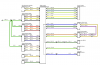
I found the wiring diagram - thanks, image attached. Out of interest what do you think the black/red + purple / dark purple channel is for, one end is open?

Charlie
Where did you get that schematic from as my version of RAVE shows it differently on both the instrument schematic and the Cooling schematic!

EDIT: Found it under the Engine Management one...

It is not indicating they are connected, all the diagram shows is the inputs/outputs to the different ECUs/Units....the schematic shows the Alternator Charging light is linked to both the Engine ECM and the Instrument Pack, similarly the Starter Motor Activation is monitored by both the ECM and the IP....just because the Purple Wire and Yellow wire are opposite the Green and Blue is pure coincidence.
 
Last edited:
Not looked at diagrams other than the one posted. But it looks to me as though the temp gauge and maybe some of the instrument pack is powered direct from alternator. Therefore and short to ground of temp gauge wire will only become apparent when alternator is supplying power.
 
Not looked at diagrams other than the one posted. But it looks to me as though the temp gauge and maybe some of the instrument pack is powered direct from alternator. Therefore and short to ground of temp gauge wire will only become apparent when alternator is supplying power.
Tony, you may have to look at the whole schematic.....

The block on the Left of the one posted with the links in is the Engine Management ECU (ECM) as far as I can tell it only indicates a link from the Starter/Alternator to the Engine ECM then to the Instrument Pack...the fact the Temp Sensor connections are drawn opposite the Alt/SM wires to the IP is coincidence to me!

I could be wrong, but I cannot think of any logical reason for the Temp gauge to be wired in with the Alt or SM.

Don't know Ant, but if the L322 is anything like the P38 were things are powered directly from the alternator after start up that maybe the cause of it only showing after the engine is running. If it has nuts and bolts and is oily i can compete with anyone. Electricary i only dabble in. :D:D
 
Here's the full schematic..

Charlie
 

Attachments

  • full-schematic.png
    full-schematic.png
    24.3 KB · Views: 121
Not looked at diagrams other than the one posted. But it looks to me as though the temp gauge and maybe some of the instrument pack is powered direct from alternator. Therefore and short to ground of temp gauge wire will only become apparent when alternator is supplying power.
Alternator output is directly connected to the battery, so unless there is an extra output or a relay driven from the D+, nothing can be driven directly from the alternator not even on an L322. However a faulty alternator should not be discounted.
 
Don't know Ant, but if the L322 is anything like the P38 were things are powered directly from the alternator after start up that maybe the cause of it only showing after the engine is running. If it has nuts and bolts and is oily i can compete with anyone. Electricary i only dabble in. :D:D
Nothing is powered directly from the alternator on the P38, the battery is always in the circuit:confused:
 
Nothing is powered directly from the alternator on the P38, the battery is always in the circuit:confused:

Fuel lift pump relay is pulled by D+ alternator whilst engine is running. It is pulled by a tap off number six glow plug when glow lamps are on. By starter relay when cranking 1999 on. Or by alternator whilst engine is running. ;)
 
Last edited:
Fuel lift pump relay is pulled by D+ alternator whilst engine is running. It is pulled by a tap off number six glow plug when glow lamps are on. By starter relay when cranking 1999 on. Or by alternator whilst engine is running. ;)
It's a polarity reversal as I see it, the alternator output is always connected to the battery, only the D+ is not, so it is not powered by the alternator, it merely senses that the alternator is producing power indicating the engine is running via said polarity reversal on the D+.
 
It's a polarity reversal as I see it, the alternator output is always connected to the battery, only the D+ is not, so it is not powered by the alternator, it merely senses that the alternator is producing power indicating the engine is running via said polarity reversal on the D+.

Yep but there was a time you said a polarity reversal in this case was not possible. :D:D
 
Yep but there was a time you said a polarity reversal in this case was not possible. :D:D
That is a matter of interpretation, the D+ line always has 12 volts via the charge indicator (or BECM in the case of the P38) which is grounded via the rotating field of the alternator to provide the initial magnetisation, as soon as the alternator starts to charge, the D+ rises to 12 volts so the indicator light has 12 volts on both sides and goes out. Not really a polarity reversal, I was merely using your term in the reply for simplicity.
 
That is a matter of interpretation, the D+ line always has 12 volts via the charge indicator (or BECM in the case of the P38) which is grounded via the rotating field of the alternator to provide the initial magnetisation, as soon as the alternator starts to charge, the D+ rises to 12 volts so the indicator light has 12 volts on both sides and goes out. Not really a polarity reversal, I was merely using your term in the reply for simplicity.

It is never the less the 12 volt coming down D+ from the alternator when the engine is running that pulls the lift pump relay. So the lift pump relay is pulled directly from the alternator. One side of charge indicator is powered from fuse #1. There cannot be 12 volt at all times in D+ or the lift pump would run when the ignition was turned on. :);)
 
Last edited:
It is never the less the 12 volt coming down D+ from the alternator when the engine is running that pulls the lift pump relay. So the lift pump relay is pulled directly from the alternator. One side of charge indicator is powered from fuse #1. There cannot be 12 volt at all times in D+ or the lift pump would run when the ignition was turned on. :);)
With the ignition on, remove the wire from the D+ and you will find it has 12 volts on it and the D+ has nothing. As I said the D+ line is grounded through the alternator until it starts charging, at which point the D+ rises to 12 volts whence it will pull the relay and extinguish the charge lamp.
 
With the ignition on, remove the wire from the D+ and you will find it has 12 volts on it and the D+ has nothing. As I said the D+ line is grounded through the alternator until it starts charging, at which point the D+ rises to 12 volts whence it will pull the relay and extinguish the charge lamp.

If with the ignition on the D+ wire from pin 15 on BECM has 12 volts on it why does the fuel pump not run with the ignition turned on? D+ goes from pin 15 BECM to D+ alternator with a tap to the fuel pump relay pull circuit via a diode. Charge lamp is actually switched off by BECM via pin 9. The description of operation in RAVE only applies to vehicles after 1999. It certainly does not apply to pre 1999 cars where the lift pump does not run on cranking. There are three ways the lift pump relay is pulled #1. Via a 12 volt tap from #6 glow plug with glow lamps active. #2. Via a 12 volt tap from starter relay on cranking. #3. Via 12 volt tap from D+ with engine running and alternator making voltage. #2 only applies to vehicles after 1999. Non of these circuits can be grounded via D+ because they are diode protected to prevent interaction, no reverse current flow can take place. So the explanation in RAVE is a little baffling. The 12 volts from starter relay when cranking cannot be grounded via D+. D+ circuit is separated from it by a diode. There cannot be 12 volt on D+ from BECM with ignition on, if there was the lift pump relay would be pulled when ignition is turn on. My head hurts. :D:D
 
If with the ignition on the D+ wire from pin 15 on BECM has 12 volts on it why does the fuel pump not run with the ignition turned on? D+ goes from pin 15 BECM to D+ alternator with a tap to the fuel pump relay pull circuit via a diode. Charge lamp is actually switched off by BECM via pin 9. The description of operation in RAVE only applies to vehicles after 1999. It certainly does not apply to pre 1999 cars where the lift pump does not run on cranking. There are three ways the lift pump relay is pulled #1. Via a 12 volt tap from #6 glow plug with glow lamps active. #2. Via a 12 volt tap from starter relay on cranking. #3. Via 12 volt tap from D+ with engine running and alternator making voltage. #2 only applies to vehicles after 1999. Non of these circuits can be grounded via D+ because they are diode protected to prevent interaction, no reverse current flow can take place. So the explanation in RAVE is a little baffling. The 12 volts from starter relay when cranking cannot be grounded via D+. D+ circuit is separated from it by a diode. There cannot be 12 volt on D+ from BECM with ignition on, if there was the lift pump relay would be pulled when ignition is turn on. My head hurts. :D:D
As I said, you will only see 12 volts on the D+ wire if it is disconnected from the alternator as it is grounded via the alternator field coils therefore it will not pull the relay untill the alternator starts to charge and produces 12 volts on the D+ terminal. That would normally turn off the charge indicator, but in the case of the P38 it signals the BECM that the alternator is charging and then the BECM turns off the charge indicator.
 
As I said, you will only see 12 volts on the D+ wire if it is disconnected from the alternator as it is grounded via the alternator field coils therefore it will not pull the relay untill the alternator starts to charge and produces 12 volts on the D+ terminal. That would normally turn off the charge indicator, but in the case of the P38 it signals the BECM that the alternator is charging and then the BECM turns off the charge indicator.

So why does the 12 volts not also ground through the lift pump relay and pull it. It cannot just disappear because it is exciting a field coil. Would make more sense if the alternator was self exciting.
 
So why does the 12 volts not also ground through the lift pump relay and pull it. It cannot just disappear because it is exciting a field coil. Would make more sense if the alternator was self exciting.
The 12 volts goes via a small bulb (or a resistor in the case of the BECM) so as I keep saying the voltage at the D+ is zero until the alternator starts to generate. As an example, connect a lamp across a battery, one side will be at 12 volts, but the other side connected to the negative pole will be at zero. There will be a parallel path through the relay but I'm not going into Ohms Law and resistances in parallel.
 
The 12 volts goes via a small bulb (or a resistor in the case of the BECM) so as I keep saying the voltage at the D+ is zero until the alternator starts to generate. As an example, connect a lamp across a battery, one side will be at 12 volts, but the other side connected to the negative pole will be at zero. There will be a parallel path through the relay but I'm not going into Ohms Law and resistances in parallel.

You seem to be missing the point that the splice to the lift pump relay is before the connection to the alternator. If on ignition 12 volts is going to the D+ terminal from pin 15 on the BECM to excite the field coils 12 volts is also going to the lift pump relay. If you have a supply then split it to two bulbs and ground both they will both light.
 
Back
Top