Series 2 Picture Request - Wiring Harness Routing

This site contains affiliate links for which LandyZone may be compensated if you make a purchase.

bazanaius

Member
Posts
74
Location
UK
Hello All,

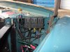
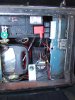
I appreciate this has a reasonable chance of turning into a thread full of birds nest photos taken off google, but I wonder if anyone has any good photos of the routing of the wiring harness, particularly in the engine bay? I'm interested in both diesel and petrol 2As.

The reason I ask... my 2A SWB started life as a petrol and at some point has had a 5 bearing diesel fitted. The wiring harness was modified to suit, and it is an absolute death trap. I'm in the process of reverse engineering what they've done via a combination of multi-meter, 3(!) of the wiring diagrams from the workshop manual and the spares manual. I then thought I'd end up having a long conversation with auto-sparks, but I'm now heading in the direction of just making my own. To do this I need to spec the lengths and distance between legs/break points etc. Given the harness is in bits in my lounge, this will be done with string on the bits of car left on my drive.

It will inevitably be a 'custom' harness, and I'm hoping to introduce some sensible improvements (dedicated earth wire to lights, breaks in useful places, a few more fuses/relays etc.) but I'd like it to at least look close to an OEM harness if someone had a quick glance in the engine bay.

I will post some details of my plans once I've transferred them from my pad to PC.
 
Mine was such a mess I cut the whole lot off and started from scratch. Like yours mine had changed from petrol to diesel. Mine is ex-mil so everything had an earth return and I kept to that. I used the basic S2A wring diagram as guide then added things that I wanted to that - intermitient wipers, hazards, reversing lights (and later a camera), front and rear fogs, 2 speed heater (almost nothing / flat out..), electric fan controls (on/off/auto), headlamp relays, front and rear interior lights, leisure batt and split charge, oil-press and volt gauges. Theres also a webasto, Teal water heater and twin tanks and a transfer pump. The challenges and mistakes were - not buying enough different colours of wire, working out what to fuse and what fuses to share - I went for 4 fuses - 1 always on and 3 via the ign but I had to move some things around to balance the loads and also for safety - so one bulb can't stop all the lights and so haz works without the key. There's a lot of holes and clips to show the routes - ie where the headlight wires cross the rad, and along the inner wing sides. I ran the loom on-top of the chassis not in it and used a made up 9 core wire to a rear junction box, that also made puttng the trailer wiring easy - std and NATO. I wrapped it in the cloth style tape and it looks ok. Whole job to 3 long days, its actually better to work fast and keep going while it makes sense, its easy to stop and forget where you are and while you are pulling one wire through you may as well pull 3 or 4.. Best bit - everything works and I've got a lot of extra functions, and the modern wires are much slimmer and carry higher currents. Most annoying, pulling 4 wires into a loom, wrapping them for about 3 ft then finding I've run 3 over the brake line and one under.. Biggest mistake - not writing up as I went along to creat a wiring manual.
 
Unless I am missing something, could you not just fit a complete diesel wiring harness, rather than trying to make your own?
 
I think it will end up being very close to one, but it has a petrol dash display and bits and bobs - plus once I'd got it apart it's so simple I think making my own will be a good opportunity to make exactly what I want/need.
 
I came to the same conclusion, I wanted to put all the earths in, add quite a few things and move the fuses inside so it didn't make sense to buy a loom only to cut it up and have to wrap new wires in. Also things like adding hazards with a second flasher are quite easy when you are making up the harness but quite tricky to retrofit.
 
Progress! I've manage to turn this:
IMG_3350_sm.jpg


Into this!
IMG_3383_sm.jpg


And lots of pages of this!
IMG_3386_sm.jpg


I think I've managed to work out most of the counter intuitive bits and at least convince myself of what I need to make it work properly rather than the mess I had. Most invaluable on top of the multimeter was the wiring diagram on the autosparks website - this is the closest I've found to a wiring diagram of what is running on my land rover 2A (1969) and a is mash up of 3 diagrams found in the workshop manual.
https://www.autosparks.co.uk/media/pdf/LR213.pdf

For those that do this in the future - label your wiring whilst it's on the car as thoroughly as possible. Put the most detail you can on a bit of tape wrapped around every spade terminal - as you unpick it all it will be essential so that you can translate it into what is on the wiring diagram. I then updated the labels on the wires as I bagged them up to reflect what I'd written in my book - the book contained a combination of wiring diagram terminology (e.g. wire colours and regulator terminals) and what I'd written when removing the wires ('top of engine rear left' became 'water temperature sender'). I missed a few wires of wrote something unreadable and that was what took the most time.

I also drew a rough diagram of what the harness looked like from above when laid out, to identify the legs and the distances between them. The new harness will be timed and specc'd to route based on some string measured on the real vehicle, but where I've removed parts in the meantime, knowing the distance to leave between LH and RH indicator/side legs will be very useful.

I'm now about to start on creating a new wiring diagram based on the auto-sparks one, to include some updates I've got planned. This has inevitable led to an afternoon of working out how some of the electrical components work - in particular the voltage regulator. Useful links I've found to help with this are:

https://matchlessclueless.com/electrical/how-it-works/lucas-voltage-regulator/
http://www.spitui.com/regulator.html
and particularly - http://www.healey6.com/Technical/The_Simple_Electronic_RB106_MK2comp.pdf

I might try and create one of the electronic regulators from the link above with an old regulator off ebay - it sounds interesting. The regulator operation is awesome - I'd not thought about it before but it is a piece of genius. Armed with some basic knowledge of what the connections mean (and discovering that I think A1 and A are connected up wrong in the autosparks diagram), I've got a question left - perhaps someone can help?

Have I understood the charge light operation correctly? When the dynamo is supplying current to the battery (i.e. the 'cut in' is active) then there is no net current flow through the charge warning light and so it is out, but when the battery is generating a greater voltage than the dynamo ('cut it' relay open) there is a path to ground through the charge light (and into the 'D' connector and out of the 'E' connector of the regulator) - and so it lights up?

Beyond that I think I get it and it all looks something a bit like this (in terms of where the various feeds go):
IMG_3388_sm.jpg


Is there a reason the majority of the lights, the 12V socket and the horn are not fused? If not I shall probably put some fuses in to protect against shorts in these circuits. I also plan to add some relays to extend the life of the lights switch and a few other bits. When the car was converted to diesel a relay for the glow plugs was added, but its huge so I'll probably try to find something a bit more compact I can hide somewhere - I'd like the vehicle to look fairly original when it's all done.

I'll post back when I've got a wiring diagram to show!

B
 
Further update I forgot about! There were several 'bonus' switches added to the vehicle when it was converted to diesel - it wasn't obvious what any of them did. It turns out one was added in the driver cubby to control the main/dip beams - was this the 'standard' place to put it? I shall need a new one as it's completely knackered - but if it's not original I'll get rid of it.

There was also a 'bonus' switch added between the panel lights and the choke pull (what will become the kill-pull) - this had been wired up to control the glow plug relay, and the 'cold start' light (explaining why the wires on the choke switch were cut off). Today I found out that the ignition switch fitted has a halfway house position to control the glow plugs, so that bonus hole can be plugged - hooray! Shame I've already painted the dash etc...
 
Further update! I've not got a dynamo, I've got an alternator fitted... with a regulator! Explains some of the other wires I found..

Not sure what to do not - I like the regulator now I know how it works, but I suspect fitting a dynamo to the 5 bearing diesel is going to be a foolish thing to do. The modifications (as per the auto sparks link above) are pretty simple. I guess I could put more fuses in the regulator and hide them that way.


I should open the regulator and look inside...
 
Ditch the regualtor, they are a work of genius in the same way a treadle sowing machine is, but they are complicated and those little contacts carry the full current and get burned so you have to carry at contact file and leave the lid loose as they only ever stop in the middle of nowhere in the dark. Most circuits are not fused as its was considered safer to keep the lights on and engine running if there were problems, that way you always got home, but a degree of driver nous is required, you must pull over at the first smell of burning and isolate the circuit ASAP. That's why dash panels tend to be very easy to remove so you can pull it down and unplug the offending wire. I always like to have a rear fog and front fog on a separate circuit so I can drive home on those if the lights go.
 
I guess ideally you would have LH head/brake on one fuse and RH on another - but then you end up with a lot of wires running the full length of the vehicle.

I've got an 'in progress' wiring diagram on the go - still some shuffling around to do though..
 
One solution that I came upon a bit late in the day on my rewire was to use fused relays for the headlights, you can site the relays near the battery and run low current to the relays with short high current wires from batt to relay then headlights. Live to relays stays on (but it is fused) but you can run the headlight feed off the ign as its a low load. Side/tail should bypass ign for parking. My electic fan is run on a fused relay as it takes 20A and I wanted short wires but the ability to override it from the dash so the fused relay is near the fan and I switch the relay earth at the dash. The other benefits of fused relays are you can work out which fuse very easily and you are adding fuses without a lot of extra wiring at the fuse box.
http://www.ebay.co.uk/itm/Fused-On-...082683?hash=item3aaf3c86fb:g:fBEAAOSwbopZVgg8
 
Now that is a good suggestion - it will drastically simplify things I think. What are your thoughts on how to handle the back of the car, particularly brake lights?


I'm wondering whether I could also use a similar setup for indicators, although the relay would have to be fairly central in the car and so wouldn't offer the same benefit for running high current wires up and down the car, it would avoid having to put that current through the indicator stalk unit. I think I'd still need the flasher unit on the 'supply' feed as otherwise it wouldn't work.


I also need to work out how my glow plugs are wired up... one for when it's light outside. But a question I can ask now - were they unfused just because they draw high current, or for any other reason?


Currently I'm planning this - :


Available at all times:

- Tail & side lights (fused relay)

- Panel lights (fused supply)

- 12V socket (fused supply)

- Interior lights (fused supply)


Only with ignition on:

- Horn (fused relay)

- Brake lights (fused relay)

- Headlights (fused relay - hoping to find a unit that will support 2 outputs rather than just on/off)

- Indicator lights (fused relay..somehow)

- Wiper (need to work out the wiring to decide how to wire this, but fused)

- Gauges (fused supply)


Unfused, ignition on only:

- Oil pressure warning lights

- Charge lights
 
You wont need to put a relay on the side / tail, they don't draw a lot and they can be on the same ciruit and fuse as the panel lights. One thing I tried that did not work was to fit LED bayonet bulbs to reduce the current, they either lasted a few weeks or had odd quirks like glowing. Re the rear, I ran a 9 wire cable to the rear and put a junction box on, then wired the lights and trailer socket off that. I used 9 to have a spare and put a live feed in for rear interior lights. If you buy it already as a cable it saves a lot of wrapping and its easy to pull along the top of the chassis. There are some clever ways to wire relays in the indicator cicuit to get hazards and trailer indicators. I think you have to use an electroninc flasher unit as the relay is a lower load. I failed to master this and used a flasher unit and a hazard unit and a relay to separate the two (so both indicatrors don't go at once when you turn). I would not fuse the heaters, the current is high and the fuse terminals will burn up. I put a 20A fuse on the cig lighter as I use a coffee maker (home made) and its draws about 19A (I have plenty of spare fuses as I need coffee) . I put in LED interior lights, these were a success - bright enough to read by and do the odd repair and a very low current draw.
Maplin do a really good DIY intermitent wiper circuit or you can find some intermiitent relays on e-bay if you can work out how to wire them. The Maplin circuit comes with a knob so you can set the delay so you have a choice of "barely wipes" and "barely wipes intermiitently", its been in a couple of years now and is still working fine. The 2 speed fan has been usefull as the fan in mine (military heater) draws a huge current and its good to be able to cut that but still have some heat, I got a really big (100W) resistor, (about 1 ohm) for a few £ off e-bay. I have a 65A alternator but that fan drops the voltage from 14.5 to 13 on its own. As mine would have had a dynamo in 1970 I assume this just flattened the battery on short journeys - it doesn't even blow a lot of air, just noise.
https://www.maplin.co.uk/p/velleman-wiper-interval-timer-solder-kit-ve03d
 
That looks a bit over the top mines a series 3 with lots of additions & some extra fuses my diagram attached. Had it 11 years and not many electrical issues .Pic by rad slam panel is lighting relays and electric fan relay. My battery is under passenger seat so some additional relays and fuses under that. Not the tidiest job under the seat but will sort it one day.
The rear door wiper/ wash and heated screen are not necesary and I probably would not do that again.
The variable speed wiper mod is good .
The electric fan automatic control has only ever operated when fully laden on a mountain track at low speed in summer, so also would not bother again.
Fogot to mention the hazards are a useful mod as is the faglight and reverse light.
 

Attachments

  • My landrover wiring Nov 2016.pdf
    1.5 MB · Views: 456
  • DSCF2583 (600 x 450).jpg
    DSCF2583 (600 x 450).jpg
    56.8 KB · Views: 3,135
  • DSCF2625.JPG
    DSCF2625.JPG
    337.9 KB · Views: 1,136
Re mods, I fitted a reversing camera and that's been good. I did it after a kid was killed at a steam fair as the rear vis on the LWB is terrible. I'm amazed / horrified at how people just walk behind it and assume I can see them.
 
All great advice and information - thanks for the replies. I've got some changes to make to my current diagram then! I think I did go overkill with the fuses - but fused relays still sound like a great idea.

Out of interest does anyone know why the tail lights are wire up to be on all the time (pin1 of lights switch)? Or have I misunderstood the switch behaviour? I would have thought they should come on along with the side lights...
 
You have misunderstood the switch, I think you have power and headlights reversed (or something like that....), the one thing certain about the switch is that it is counter inuitive
 
Ok I think that makes more sense - so pins 1 and 7 (panel, side, tail) are always joined together. In pos 1 nothing is on (no connection to pin 4, power). Pos 2, everything but head lights are on, and in Pos 3 headlights are on too.

I need to double check my switch again - it may work like that after all.

Counterintuitive is not the word - it's just mental!
 
Back
Top