You are using an out of date browser. It may not display this or other websites correctly.
You should upgrade or use an alternative browser.
You should upgrade or use an alternative browser.
Series 2 Picture Request - Wiring Harness Routing
- Thread starter bazanaius
- Start date
This site contains affiliate links for which LandyZone may be compensated if you make a purchase.
- Posts
- 83,310
- Location
- Embasinga stocæ

British Standards Institution # BS-AU7 Colour Code for Vehicle Wiring
The British Standards institution (BSI) creates and maintains standards for British industries, one of which is colour coding automotive wire insulation based upon the use of the wire. This is a great help to those of us maintaining our own British cars allowing us to glance at a wire and know what it is being used for. This standard is periodically updated as vehicles become more complex with more colour combinations used and in some cases the uses are changed for a colour combination. Colour code tables for BS-AU7a (1983 revision) and newer are commonly available on the net. What I am trying to document is colour uses for 1960's and earlier British cars. I may miss some colours & some uses. Series III Land Rovers have a more complicated wiring system using additional coloured wires, but most of the uses remain the same as called out in this page. Additionally, replacement wire harness manufacturers have to pick a version of the standard for building their looms and the version they use may be newer than what your vehicle was originally built to so some insulation colours might not match what your vehicle had from the factory.
I have added some newer standard codes for accessories that might be added to a series Land Rover, such as rear fog lamps, a rear window wiper and washer, driving lamps, radio and electric fan. In general solid colours go from the power source to a switch and a stripped wire goes from the switch to the switched electrical component. If you have a newer vehicle with more a more complicated electrical system here is a link to a chart that covers newer vehicles as outlines in a newer version of the colour code.
Please note that Land Rovers built to military specifications use a different wire colour code.
Source for colour coded wires, wire harnesses, connectors and tools in the US: British Wiring
Black
All ground connections
Black/ Purple
Temperature switch to warning light
Black/ Green
Relay to radiator fan motor, windscreen wiper switch to single speed wiper motor.
Black/ Light green
Brake switch
Black/ Light green
Brake differential pressure valve to warning light
Black/Orange
Radiator fan motor to thermal switch
Black/red
From 3 prong flasher unit to flasher light
Black/white
Flasher unit light to ground
Blue
Headlamp connections
Blue
Headlamp switch to dimmer switch
Blue White
Headlight high beams, Dimmer switch to long-range driving light switch
Blue/ White
High beam dimmer switch to high beam indicator lamp
Blue/ light green
Windscreen wiper switch to motor
Blue/ Red
Headlight low beams
Blue/ Yellow
Long range driving lamp switch to lamp
Brown
Main feed from the battery. No switches or fuses
Brown/Yellow
GEN 'D' to volt. Regulator 'D'. Ignition warning light
Brown/ Blue
power feed to headlamp switch and voltage regulator to ignition switch
Brown/ White
Ammeter to main alternator terminal, or voltage regulator
Brown/ Yellow
Alternator to 'no charge' warning light
Brown/ Purple
Alternator Regulator feed
Brown/ Green
Fuse to horn (No relay), Generator 'F' to voltage regulator 'F'
Brown/ Lt. Green
Windscreen wiper motor to switch
Brown/ Black
Horn to horn button (no relay)
Green
Ignition switch controlled wiring for auxiliary devices, switched 12V to individual wiper motors, to brake lite switch, flashers, etc
Green/ Black
Fuel gauge to fuel tank unit (Light green/black for vehicles with voltage stabilizer)
Green/ Orange
fuel low level warning light to sensor on fuel tank
Green/ Slate
Heater motor to fast position on 2 speed heater swtch
Green/ Blue
Water temperature gauge to temperature sender unit (Light green/black for vehicles with voltage stabilizer)
Green/ Blue
low fuel warning light to fuel sender unit.
Green/ Brown
Switch to reverse lamp
Green/ Red
Direction indicator switch to left-hand flasher lamps
Green/ Purple
Stop lamp switch to stop lamps
Green/ White
Direction indicator switch to right hand flasher lamps
Green/ Yellow
Heater switch to slow speed on heater motor or for single speed motor
Green/ Yellow
oil pressure light to oil pressure switch
Green/ Gray
Heater switch to high speed on heater motor
Light green
voltage stabilizer to instruments on LRs fitted with voltage stabilizer
Light green
choke cable mechanical switch to carburetter heater element (Solex optional fitment)
Light green/ Black
Windscreen washer switch to washer motor
Light green/ Blue
Flasher switch to left-hand flasher warning light
Light green/ Yellow
Flasher switch to right-hand flasher warning light
Light green/ Brown
Flasher switch to flasher unit 'L'
Light green/ Purple
Flasher unit 'F' to flasher warning light
Light green/ Orange
Rear window washer switch to motor
Light green/ Red
fuel mixture light to fuel mixture thermostat switch (vech. with carb heater)
Orange
Wiper circuit (single motor wiper system)
Orange/ Black
Wiper switch to to motor parking
Orange/ Blue
wiper switch to low speed on motor
Orange/ Green
Wiper switch to high speed on motor
Orange/ Yellow
Rear wiper switch to rear wiper motor
Orange/ Light green
switch to rear window motor parking
Purple
Accessories fed direct from battery via fuse (Always live)
Purple/ Brown
Horn fuse to horn relay when horn is fused separately
Purple/ Red
Switches to map light, under bonnet light, glove box light and boot lamp when fed direct from battery fuse
Red
Tail lights, instrument lights, parking lights and side markers
Red/ Yellow
Fog light switch to fog light or front fog light fuse to fog lights
Red/ Blue
Front fog light fuse to fog light switch
Red/ Brown
Rear fog guard switch to lamps
Red Orange
Power to rear fog guard lamp fuse
Red/ White
Fuse to instrument lamp switch, Instrument panel lamps
White
Ignition circuit, no additional switches, not fused
White
Power to coil, fuse to cold running light (vech. w/o carb heater)
White
Power to electric fuel pump
White/ Black
Ignition coil to distributor
White/ Black
Distributor side of coil to tach impulse sensor
White/ Black
mechanical choke cable mounted switch to cold running thermostat switch (1960's vech. w/o carb heater)
White/ yellow
mechanical switch on choke cable to thermostat switch( in 1970's, white black earlier)
White/ Brown
Oil pressure switch to warning light or gauge
White/ Blue
cold runing light to mechanical switch on choke cable (vech. w/o carb heater) (light blue in 1970's)
White/ Pink
Ignition switch to radio fuse
White/ Red
Ignition switch or starter switch to starter solenoid
Yellow
Generator connections wired through the ignition switch and electric overdrive wiring
Yellow
Dynamo 'D' to voltage regulator 'D', Voltage regulator 'D' to gen. light on instrument panel
Yellow/ Green
Dynamo 'F' to control box 'F' Alternator field 'F' to control box 'F'
Yellow/ brown
yellow/Blue
Yellow/Rd
Yellow/purple
Yellow/Gren
Overdrive related wiring
Note that this is an abreviated list showing colours most likely encountered on a Series Land Rover and circuits a Series Land Rover owner is likely to add to their vehcle. Here is a link to a colour code chart that covers newer vehicles with more electronics.
Aproximately equivelent wire sizes and capacities:
British standard
U.S. standard
AMP carrying
capacity
General
uses
14 strand
18 gauge
8 amps
tail & side lamps. general instrument wiring
28 strand
14 gauge
17 amps
Headlamps, horns, Aux lighting
44 strand
12 guage
25.5 amps
Generator to Control box & Ammeter
65 strand
10 guage
35 Amps
30 AMP alternator feed & ammeter
Generator voltage regulator connections:
Early positive earth voltage regulator with 5 posts
Regulator
post label
wire
colours
Go to
AL
Brown/Blue
2 wires
A contact ign sw.
Fuse block (always hot fuse
A
Brown/White
Amp meter
F
Yellow/Green
F terminal Generator
D
Yellow
2 wires
D terminal Generator
Gen light in panel
E
Black
Ground
Neg earth IIA voltage regulator with 3 posts
Regulator
post label
wire
colours
go to
B
Brown/White
Amp Meter
F
Yellow/Green
F terminal genertor
D
Yellow
2 wires
D terminal Generator
Gen light in panel
Flasher pin code:
Flasher units have to be connected to the turn signal switch circuit in a certain way and are marked in a way that is far from obvious. So here are the markings and where they go for a 3 prong flasher unit. The same code works for the 2 pin flasher as well.
Flasher pin label
What it connects to
X
Switched 12 V (green wire)
L
Power to turn signal lights
P
power to flasher indicator light
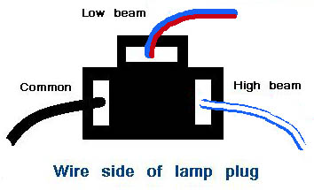
Headlamp socket:
Sometimes you might purchase a replacement headlamp socket from a company that provides pig tail leads that do not follow ther British standard and you need to figure out which circuit each lead needs to be connected to.
- Posts
- 83,310
- Location
- Embasinga stocæ
Accessories fed direct from battery via fuse (Always live)
Purple/ Brown - Horn fuse to horn relay when horn is fused separately
Purple/ Red - Switches to map light, under bonnet light, glove box light and boot lamp when fed direct from battery fuse
what are you powering?
Purple/ Brown - Horn fuse to horn relay when horn is fused separately
Purple/ Red - Switches to map light, under bonnet light, glove box light and boot lamp when fed direct from battery fuse
what are you powering?
I've added a fuse for the supply to the light switch and the 12V socket. Off the same feed as the light switch I'm powering the horn push which will actuate a relay at the front of the car. These feeds would have originally been brown, as unfused always on - but now they're fused, but always on I don't know what to colour them.
For now they're green in my diagram - attached!
Does anyone know what rating the resistor is in the heater 2-speed circuit? Or is this built into the heater unit (I have the flat, rectangular heater unit)?
Anything I've missed, or got the colour/routing wrong for?
For now they're green in my diagram - attached!
Does anyone know what rating the resistor is in the heater 2-speed circuit? Or is this built into the heater unit (I have the flat, rectangular heater unit)?
Anything I've missed, or got the colour/routing wrong for?
Attachments
What drawing package did you use for that it looks good ,mine was an original pic from manual painstakingly altered overtime as a pdf using pdf writer.
Have wanted to make a simple single line schematic for ages , used to simplify lots of wiring diagrams when I worked in the mining industry.
Was dam nigh impossible to use full diagrams due to the working conditions.
Have wanted to make a simple single line schematic for ages , used to simplify lots of wiring diagrams when I worked in the mining industry.
Was dam nigh impossible to use full diagrams due to the working conditions.
rob1miles
Well-Known Member
- Posts
- 3,565
- Location
- Slough and Bath
That drawing looks nice, makes me think I aught to think about drawing mine up the same way. I didn't keep enough notes and a few weeks ago I had an odd problem, luckily I quickly tracked to a correoded fuse, but if the fault had been harder to find I'd have been struggling to follow the wiring even though I did it all. It made sense 4 years ago but thats not the same as remembering it.
I did it in Microsoft Visio, as it was already installed on my work laptop - but unfortunately it's not free. The icons were a combination of screenshots from various things like Google images etc, and some I drew myself (e.g. relays).
It was OK - a bit fiddly in places (e.g. multicolour dashed wires) but worked well.
The schematic is... A ball ache. I think I might be better off making it 'on-car' rather than trying to design it a in advance. I'm just not sure it's an efficient use of my time!
Anyone got any info about the resistor for the heater speed control?
Have a look here sounds about right I have some readings written down but will need to find them.
http://www.mgb-stuff.org.uk/heater.htm
http://www.mgb-stuff.org.uk/heater.htm
rob1miles
Well-Known Member
- Posts
- 3,565
- Location
- Slough and Bath
The restor values are around the 0.5 to 1 ohm range, how much they drop the speed depends on how much current the fan draws so its a bit hit and miss. Be ware of the load rating. The 10 - 11Watt ones are ok in the airflow as this keeps them cool, but if you want it somewhere else then you can get a finned 100W one for under £2:
https://www.ebay.co.uk/itm/Chassis-...198623&hash=item3d52ef881f:g:gswAAOSwVNxaL--Q
I think that could be the one I used, I not sure now but at £1.18 its not a big loss, if you can find a 0,5 0hm I would get that and the 1 ohm..
https://www.ebay.co.uk/itm/Chassis-...198623&hash=item3d52ef881f:g:gswAAOSwVNxaL--Q
I think that could be the one I used, I not sure now but at £1.18 its not a big loss, if you can find a 0,5 0hm I would get that and the 1 ohm..
Updated wiring diagram attached, now to include a washer bottle switch/motor which I'd forgotten.
Also attached a schematic showing where the harness will go/branch and break points (green blocks).
Schedule to come...
Also attached a schematic showing where the harness will go/branch and break points (green blocks).
Schedule to come...
Attachments
rob1miles
Well-Known Member
- Posts
- 3,565
- Location
- Slough and Bath
I did by using a 2 way momentary make toggle so one way is washer and the other is flash. Its far from ergonomic and not ideal but the wires were right by the switch and I had one to hand. It does get used, mostly to flash trucks overtaking me on the motorway, but there's a 50% chance of washing the windscreen at them.
Can you tell what it is yet? A nice day for taping bits of string all over what's still outside on the landy - got some strange looks from the neighbours, but I think I've got all the measurements I need.
Ended up with some tweaks to the harness layout diagram to avoid sending wires over the exhaust headers etc. Will post an updated diagram once I've transferred the measurements on as well.
I wasn't planning on having a flasher switch - it ends up being quite a bit more complicated, and the dip/main switch will be quite close by when driving.
Realising I don't have a dedicated washer switch and my wiper switch only has 2 positions, I'm considering changing what is currently my wiper switch for a similar type to the lights/heater switch.
On the single speed wiper connector, there is a green and an earth, and then a green/red and a green/brown. I think the green/red is 'run' and the green/brown is 'park' - is this correct? Also, to get park to work I need to connect it to power; is it OK to keep this always powered except when the motor is running, or does the normal wiper switch do something special other than just connect it to power when in the off position?
On the single speed wiper connector, there is a green and an earth, and then a green/red and a green/brown. I think the green/red is 'run' and the green/brown is 'park' - is this correct? Also, to get park to work I need to connect it to power; is it OK to keep this always powered except when the motor is running, or does the normal wiper switch do something special other than just connect it to power when in the off position?
rob1miles
Well-Known Member
- Posts
- 3,565
- Location
- Slough and Bath
The wiper switch is a 2 pole switch with the 12v to common. It then switches between park and run. Run goes staight to the wiper motor, park goes through the park switch then to the wiper motor. The park switch is also a 2 pole switch with the motor on common and the contacts to the wiper switch and earth. The way it works is wiper is stopped on park, switch on and the motor gets power, the park switch gets live and sends this back to the wiper swicth but its OK because the contact is open. Switch off and the wiper gets its supply through the park switch until it hits the stop, then it switches the motor from live to earth, this stops the motor quickly. If its doesn't switch the motor to earth it won't stop quickly enough before the cam passes the switch and the wipers will keep running. Becuase the wiper switch is always live and the park switch grounds the motor to earth you can get an alighy short if you wire it up wrong so double check. Take the wiper supply via a relay off ign so its dead when the ign is off.
Similar threads
- Replies
- 1
- Views
- 655