Hi everyone. I need a little bit of info that will be useful for what I'm about to do.
To begin with, I have been scouring the LandyZone site for information regarding replaceing my FL1's, Water Pump + Thermostat, both drive belts and servicing the 'leaks-when-cold' HP Injector Fuel Pump. All 3 will be done together, especially as each job seems to overlap the others.
I'm getting all the parts and special tools I need (I should buy shares in Ebay), oils, etc, too. I've even copied the relevent information with accompanying pictures for each project, so referencing should be easy. All these little bits of information is absolutely invaluable, so thanks to all the LandyZone contributers. It's a great team effort.
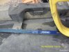
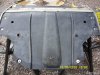
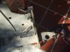
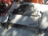
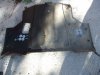
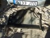
The one little bit of information I need is... the Engine Undertray on my FL1 has two mounting-bolts at the rear and four rivets, 2 at each side. I'm guessing there should be two screws on each side instead, supposing a garage has at somepoint fitted the rivets as perhaps the screws were knackered. It's a professional job and if I'm correct I'll need to drill 'em out and replace them with screws instead. A hole was cut where the Engine Oil Sump plug could be accessed. Very clever.
So, should there be screws instead of rivets? I've already tried to remove the stubborn tray but these rivets are solid, as is the tray in consequence.
My Haynes manual only ever refers to 'removing the tray', but doesn't seem to give any great level of details. Help?
To begin with, I have been scouring the LandyZone site for information regarding replaceing my FL1's, Water Pump + Thermostat, both drive belts and servicing the 'leaks-when-cold' HP Injector Fuel Pump. All 3 will be done together, especially as each job seems to overlap the others.
I'm getting all the parts and special tools I need (I should buy shares in Ebay), oils, etc, too. I've even copied the relevent information with accompanying pictures for each project, so referencing should be easy. All these little bits of information is absolutely invaluable, so thanks to all the LandyZone contributers. It's a great team effort.
The one little bit of information I need is... the Engine Undertray on my FL1 has two mounting-bolts at the rear and four rivets, 2 at each side. I'm guessing there should be two screws on each side instead, supposing a garage has at somepoint fitted the rivets as perhaps the screws were knackered. It's a professional job and if I'm correct I'll need to drill 'em out and replace them with screws instead. A hole was cut where the Engine Oil Sump plug could be accessed. Very clever.
So, should there be screws instead of rivets? I've already tried to remove the stubborn tray but these rivets are solid, as is the tray in consequence.
My Haynes manual only ever refers to 'removing the tray', but doesn't seem to give any great level of details. Help?