Failed alternator (again)!

This site contains affiliate links for which LandyZone may be compensated if you make a purchase.

SteveG4TRA

Active Member
Posts
203
40 miles ago I fitted a replacement alternator, the RollCom ALT336 from Advanced Factors. After a bitch of a job I got her in and all was fine for 40 miles, now the charging (battery) light does not go out. Its on all the time when the ignition is on.

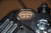
Sure enough without the battery connected she will not run and having manged to get back down to the alternator there are no volts coming out of the main output terminal of the alternator.
Now it is impossible to get back to the connector on the back to do a check there without stripping the whole side of the engine and removing the alternator again and that is a pain.

I need to check that that there is a 12v excitement feed going to the alternator from fuse 24 in the passenger compartment which is good, through Header 0287(K109), but where the hell is Header 0287(K109).

Anybody any ideas before I rip this damn 40 mile alternator out?

Thanks' in anticipation

Steve
 
You may find this information useful as you can download these as pdf files if you search for them.

LRL 0529 ENG 3
Discovery 2 my99 to my03 electrical Library
(This will show you where connector 0287 is, be aware this is shown as lhd and rhd models so check).

LRL 0436 ENG 2
Circuit diagrams 00my red

Vrd 100090 ENG (6)
Workshop manual 1999 my on
Hi Roy,
Thanks for the information.
I decided not to wait, and ripped the damn thing out, I had done it a month or two back and it should be a lot quicker this time. Sure enough I got the unit out, connected a battery up, turned the ignition in and measure down at the centre pin (white/green) the exciter terminal of the multi pin plug and sure enough there was 12v there.

So that then pointed the fault at the alternator itself, the bright shiny 4 month old replacement unit sitting smugly on the bench. Luckily I had kept the old (original) unit, which had failed on the vacuum pump, electrically it was fine) and was able to compare all static resistive readings between the two unit on all pins, they read the same on both unit. So electrically at least the alternator and vehicle we correct.

It was then I noticed that the centre pit of the alternator mulit-pin socket was shorter by about 5mm that the other two pins in the housing. This was not the case in the old unit, all pins were at the same length. It was not a case that the pin had been pushed into the unit, for it was moulded and immovable. This alone would explain the intermittent nature of the fault.
Now it looks like I have to find a replacement for my 40 mile alternator.
 
Based on all your statements untill now it seems that you are quite handy with it just be aware that the following statement of yours
I need to check that that there is a 12v excitement feed going to the alternator from fuse 24 in the passenger compartment which is good,
is not correct cos the td5 alternator has no ''excitement feed" , it's a 3 phase auto exciting thing, that F24 is to protect the alternator so forget about that and about that hidden header C0287 cos the alternator should deliver power even with F24 removed... i think that the alternator was DOA as long as you dont gt at least 14V on the battery with engine running..eventually check continuity of maxi FL1 in the engine bay fusebox to rule it out

here is from the electrical library:

Charging Operation
With the ignition switch in position II, the feed from fuse 24 is connected from the passenger
compartment fusebox, through header C0294 LHD/ CO287 RHD, to connector interface
C0448-4/C0162-4 on a W wire. From the connector interface the feed is connected on a WG
wire to the alternator/generator.
This feed protects the alternator/generator from short circuit
damage should a wiring fault occur.

The feed from fuse 27 is connected from the passenger compartment fusebox on an LG wire
to the ignition/no charge warning lamp in the instrument pack, via header C0760. From the
instrument pack, the feed is connected on an NY wire to the alternator/generator, via header
C0294 LHD/C0287 RHD.
The feed passes to earth via the brushes and regulator within the alternator, completing the
warning lamp circuit which allows the warning lamp to illuminate.
When the engine is started, the magnetized rotor turns within the stator windings, generating
3 phase alternating current (ac) and a voltage that rises rapidly with rotor speed. The field
diodes in the rectifier pack convert the ac current into dc current flowing through the field
windings.
This causes an increase in the magnetic influence of the rotor, resulting in self excitation
of the alternator. The field current increases with rotor speed and thus increases
the generated current and voltage until the alternator/generator is fully excited.
When the voltage applied to the alternator/generator side of the ignition/no charge warning
lamp exceeds the battery voltage applied to the warning lamp, the lamp is extinguished. This
shows that the alternator/generator is producing battery charging current.
When the battery is at a low state of charge or the current draw from the electrical functions
of the vehicle causes a voltage drop, the alternator/ generator automatically charges at its
maximum rate (dependant on rotor speed) until 14 Volts is reached. When demand on the
alternator/generator falls, the current output is reduced.
Battery charging is accomplished on an N wire from the alternator/generator through fusible
link 1 in the engine compartment fusebox, and from fusible link 1 to the battery positive
terminal on an R wire.
 
Last edited:
Based on all your statements untill now it seems that you are quite handy with it just be aware that the following statement of yours
is not correct cos the td5 alternator has no ''excitement feed" , it's a 3 phase auto exciting thing, that F24 is to protect the alternator so forget about that and about that hidden header C0287 cos the alternator should deliver power even with F24 removed... i think that the alternator was DOA as long as you dont gt at least 14V on the battery with engine running..eventually check continuity of maxi FL1 in the engine bay fusebox to rule it out

here is from the electrical library:

Charging Operation
With the ignition switch in position II, the feed from fuse 24 is connected from the passenger
compartment fusebox, through header C0294 LHD/ CO287 RHD, to connector interface
C0448-4/C0162-4 on a W wire. From the connector interface the feed is connected on a WG
wire to the alternator/generator. This feed protects the alternator/generator from short circuit
damage should a wiring fault occur.
The feed from fuse 27 is connected from the passenger compartment fusebox on an LG wire
to the ignition/no charge warning lamp in the instrument pack, via header C0760. From the
instrument pack, the feed is connected on an NY wire to the alternator/generator, via header
C0294 LHD/C0287 RHD.
The feed passes to earth via the brushes and regulator within the alternator, completing the
warning lamp circuit which allows the warning lamp to illuminate.
When the engine is started, the magnetized rotor turns within the stator windings, generating
3 phase alternating current (ac) and a voltage that rises rapidly with rotor speed. The field
diodes in the rectifier pack convert the ac current into dc current flowing through the field
windings. This causes an increase in the magnetic influence of the rotor, resulting in selfexcitation
of the alternator. The field current increases with rotor speed and thus increases
the generated current and voltage until the alternator/generator is fully excited.
When the voltage applied to the alternator/generator side of the ignition/no charge warning
lamp exceeds the battery voltage applied to the warning lamp, the lamp is extinguished. This
shows that the alternator/generator is producing battery charging current.
When the battery is at a low state of charge or the current draw from the electrical functions
of the vehicle causes a voltage drop, the alternator/ generator automatically charges at its
maximum rate (dependant on rotor speed) until 14 Volts is reached. When demand on the
alternator/generator falls, the current output is reduced.
Battery charging is accomplished on an N wire from the alternator/generator through fusible
link 1 in the engine compartment fusebox, and from fusible link 1 to the battery positive
terminal on an R wire.

The plot thickens...…
Firstly removal of fuse 24 and the vehicle will not start, turns over but will not start. Take fuse 24 out when the vehicle is running and the engine stops.
So why is that happening when This feed protects the alternator/generator from short circuit damage should a wiring fault occur. I'm a bit lost here.

The alternator did work for 40 or so miles, the battery charge lamp was out OK. So my guess is that the alternator was working as it should do.

I measured down on the main brown lug output of the alternator with the engine running , there was just 11.9 battery volts. Disconnect the battery and the engine stops. I also checked the Link 1 150 amp and as expected that is OK. I have also measured resistances statically of the alternator out on the bench with another unit that was working fine before and they all pins/lugs check out the same on both alternators.

Apart from the potential manufacturing fault on CO226-2, the fuse 24 feed I am now lost...….help!
 

Attachments

  • DSC_0347.JPG
    DSC_0347.JPG
    174.9 KB · Views: 467
I was a bit wrong about F24 cos i missed that it's a feed for the engine ECU(and autobox ECU too on autos), so it's normal for the engine to stop with F24 removed cos that's how it protects the main feed in case af a short circuit as it's conceived to stop the engine if it blows before the vehicle ends up in flames... what's certain is that if the feed from it to the alternator is cut it doesnt affect the charging so i insist that as long as you dont get 14V to the battery from the alternator's main output you can send it back and ask for another, resistance checks are irrelevant in this case, C0658 - 33 is ECM ignition feed, C0226-2 ia on the alternator and even if you cut it the alternator should give charge

F24.jpg
 
Last edited:
The plot thickens...…
Firstly removal of fuse 24 and the vehicle will not start, turns over but will not start. Take fuse 24 out when the vehicle is running and the engine stops.
So why is that happening when This feed protects the alternator/generator from short circuit damage should a wiring fault occur. I'm a bit lost here.

The alternator did work for 40 or so miles, the battery charge lamp was out OK. So my guess is that the alternator was working as it should do.

I measured down on the main brown lug output of the alternator with the engine running , there was just 11.9 battery volts. Disconnect the battery and the engine stops. I also checked the Link 1 150 amp and as expected that is OK. I have also measured resistances statically of the alternator out on the bench with another unit that was working fine before and they all pins/lugs check out the same on both alternators.

Apart from the potential manufacturing fault on CO226-2, the fuse 24 feed I am now lost...….help!

Further investigation shows that F24 also feeds the ECU which would explain why the car wont start without it and at rest draws 150mA.
Now if this feed to the alternator on the white wire was open circuit (via the faulty alternator connector pins) then, and I am guessing here, the alternator goes into protection mode and will not produce any output? If it was connected then it would sense the battery voltage and adjust the alternator output accordingly . Maybe this is the battery sense input (not the exciter feed I called it).

If that sounds sensible then I have the fault, as in the picture with the short pin.
 
I think i explained in my previous post, the purpose of F24 being conncted to the alternator is to stop the engine if a short within the alternator(generator) occurs and blows the fuse,
I am guessing here, the alternator goes into protection mode and will not produce any output?
IMO the generator should deliver voltage regardless of that wire connected to F24 or even with that connector from your pic disconnected cos it generates voltage when the magnetised rotor is turning within the stator when the engine is running though a short within the alternator can generate fire if the engine keeps spinning it that's why it's supposed to stop ... maybe i'm wrong but i'm convinced that your problem is not on F24's path to the alternator at all but you was unlucky enough to get an unreliable alternator.
 
I think i explained in my previous post, the purpose of F24 being conncted to the alternator is to stop the engine if a short within the alternator(generator) occurs and blows the fuse,
IMO the generator should deliver voltage regardless of that wire connected to F24 or even with that connector from your pic disconnected cos it generates voltage when the magnetised rotor is turning within the stator when the engine is running though a short within the alternator can generate fire if the engine keeps spinning it that's why it's supposed to stop ... maybe i'm wrong but i'm convinced that your problem is not on F24's path to the alternator at all but you was unlucky enough to get an unreliable alternator.
I think between us we'll sort this and I agree that the function of F24 is to take volts from the ECU and stop the engine. Agreed.
So it leaves the question as to where the voltage sense come from, for without that the alternator would boil the battery. It can only come from FS24 or FS27? Cant believe it come via the ignition/charge light?
But I may be wrong?
Maybe the white wire from Fuse 24 serves two functions, protection and detect?
 
... where the voltage sense come from, for without that the alternator would boil the battery.
there is no such thing on a D2, if the alternatopr fails it will noit charge not boil the battery...in the unlikely case that it fails on a misterious way as to give too high output the current will grow due to the battery's resistance and will blow the fusible link
 
there is no such thing on a D2, if the alternatopr fails it will noit charge not boil the battery...in the unlikely case that it fails on a misterious way as to give too high output the current will grow due to the battery's resistance and will blow the fusible link
The alternator has now been changed (again) and the vehicle is working as it should do.
The fault was that the centre pin of the three way connector was incorrectly positioned at the manufacturing stage so partially disconnecting the 12v feed from F24 to the alternator. My assessment is that the alternator regulator system uses this as a reference voltage and without will not work. Any alternator with inbuilt regulation needs a reference voltage to work against, which in this case is provided from F24.
The existing alternator was fine apart from the fact that there was no 12v coming into the unit from F24 due to the faulty pin. All static checks on the unit as compared to a known working unit supported this theory.
The other pin incidentally is connected to the dashboard batter/charge light. The alternator provides an earth when the alternator is not rotating with ignition on, and as the alternator turns, up to 12v to extinguish the light showing the battery is being charged.
 
Ok m8, i'm glad it's working and we can agree that we disagree on that while i know exactly how the alternator works and i sustain that your theory is wrong.
 
Ok m8, i'm glad it's working and we can agree that we disagree on that while i know exactly how the alternator works and i sustain that your theory is wrong.
I think I have got to the bottom of this, having been talking to the techies at Denso. Firstly the DAN670 (ERR699) alternator is not a self exciting alternator. It works by an Initial Self Excitation Function, ie 12v from Ignition switch on Pin 2 of the rear connector. Denso state it will not work without an initial Self Excitation Function. That said, then my initial assumption that the alternator will not work without 12v on Pin 2 is correct.

In so far as regulation goes I was incorrect in my assumption that pin 2 provides this function. The regulation is done internally in the alternator depending current demand, ensuring the right voltage appears at all times on the main output. Not the best way but adequate.

Now we come to the statement in the Rave manual referring to Pin 2 stating This feed protects the alternator generator from short circuit damage should a wiring fault occur. I think this is miss-leading as Denso state that the DAN670 has internal alternator Malfunction Detection Functions. If there is a open or short in the regulator circuit, the alternator will not charge and regulator will turn the charge light ON on dashboard. Additionally should there be a short on the wiring to Pin 2 then Fuse 24 will blow and if there is a permanent 12v on Pin 2 then other dash lights would appear I guess as for one there would be 12v permanently on the Ignition and EMU for instance.

Maybe the Rave manual should be amended to read This feed provides initial excitation12v from the ignition switch. The alternator generator is protected internally from alternator malfunctions. If there is a open or short in the regulator circuit, the alternator will not charge and regulator will turn the dashboard charge light ON.
 
Back
Top