Yes it is. The battery is a HD Yuasa YBX3642: link. I do not use the winch often and it is more for moving things around, on and off trailers etc than for self recovery. I have never had a problem with using the same battery, the winch is only run with the engine running and I have a 100amp alternator. I have never had it happen but if I needed to stop a pull to let the battery recharge that is not a problem, it is not a competition truck and speed has never been a requirement. The winch itself also reflects this as well by being a worm drive husky, reliability and simplicity over speed. Same with a large high rated single battery over two needing a split charge system.The starting battery is also the winch battery?
You are using an out of date browser. It may not display this or other websites correctly.
You should upgrade or use an alternative browser.
You should upgrade or use an alternative browser.
Burnt out - rebuild
- Thread starter dag019
- Start date
This site contains affiliate links for which LandyZone may be compensated if you make a purchase.
- Posts
- 5,082
The starting battery is also the winch battery?
Yes, tis on mine anyway - why would you need a second one and where would you put it ?
- Posts
- 5,082
<snip> My reasons for wanting LED headlights are to reduce the load on the wiring circuit, I have replaced other lights with LEDs as part of my rebuild (link) after the engine fire caused by electrical fault. I am aware of the boomslang harness but having ordered one before the fire to fit I found it poorly made, and not well though through in terms of the positioning of things. I did begin to modify it for improvement but gave up as it was going to cost more to modify than to start from scratch. I currently have brand new wiring looms throughout as part of the rebuild so this is not a “my headlights are dim” type thread because the writing is in poor condition and 30 years old.
<snip>.
Personaly I think LED's look totaly wrong/out of place.
They are also remarkably easy to steal if you think about it ....
Make your ownboomslang up. I bought 4 fused relays from eBay (£8 I think) and wired them in so that the lights are fed directly from the aux circuit and the 'wiring circuit' now only provides 12V at around 30mA.
I put my relays under the (false) vent on the offside wing ....
Seaswood
Active Member
- Posts
- 242
- Location
- Falmouth New England
I have old winch waiting someday & would prefer one battery.
On this side you see a lot of double batteries, but yes what for.
On this side you see a lot of double batteries, but yes what for.
mick the builder
Well-Known Member
- Posts
- 5,901
- Location
- Sligo,Wild West of Ireland.
Any chance of a sketch of your boomslang and how you wired it in with the relays?Personaly I think LED's look totaly wrong/out of place.
They are also remarkably easy to steal if you think about it ....
Make your ownboomslang up. I bought 4 fused relays from eBay (£8 I think) and wired them in so that the lights are fed directly from the aux circuit and the 'wiring circuit' now only provides 12V at around 30mA.
I put my relays under the (false) vent on the offside wing ....
View attachment 282944
- Posts
- 5,082
Any chance of a sketch of your boomslang and how you wired it in with the relays?
I think I posted this already but I can't find it and to be honest can't remember what I had for breakfast last week .....
Anyway ...
The relays are clipped together mounted on a board and bolted to the inner wing, all 4 Pin85's are connected to the bolt on the inner wing (ground)
All Pin30's are connected to a feed from the Aux connector on the back of the ignition swich.
I used a 2mm2 cable from the ignition switch to Pin30 (25A) and joined them all together (Red)
I took off the eyebrows and located the light cables.
I cut the cable to the High beam and connected the wire from the light switch to Pin86 and Pin87 to the cable that went directly to the bulb.
I used 2mm2 cable to the bulb (Pin87) and 1mm2 cable to the relay (Pin86)
I did the same with the Dip beam.
I copied that on the Near Side running the cable along the inner wing, behind the heaters air intake, across the bulkhead, around the brake servo and to the relays. There are already cables running across there so used the existiing cable ties etc.
I used Lucas connectors on the cables.
Looking at my picture (above) Red is AUX power in (Pin30) White is Pin86 (switch), Blue is Pin87 (bulb). The Black earth wires tuck underneath and goto the inner wing (ground), the Green wires are not used (I bought 5 pin relays as they had a 10A fused input).
These are similar to the relays I bought. https://www.ebay.co.uk/itm/402118584366
Last edited:
As long as you don't run the winch without the engine running there is no need for a second battery in my opinion. the whole point of having a second battery for auxiliary things is to protect the starter battery so it does not drain and you can always restart and drive. I cant think of many situations where you would be wanting to winch without the engine running.I have old winch waiting someday & would prefer one battery.
On this side you see a lot of double batteries, but yes what for.
Seaswood
Active Member
- Posts
- 242
- Location
- Falmouth New England
Like you said just to pull things around the yard.
mick the builder
Well-Known Member
- Posts
- 5,901
- Location
- Sligo,Wild West of Ireland.
Brilliant cheers.I think I posted this already but I can't find it and to be honest can't remember what I had for breakfast last week .....
Anyway ...
The relays are clipped together mounted on a board and bolted to the inner wing, all 4 Pin85's are connected to the bolt on the inner wing (ground)
All Pin30's are connected to a feed from the Aux connector on the back of the ignition swich.
I used a 2mm2 cable from the ignition switch to Pin30 (25A) and joined them all together (Red)
I took off the eyebrows and located the light cables.
I cut the cable to the High beam and connected the wire from the light switch to Pin86 and Pin87 to the cable that went directly to the bulb.
I used 2mm2 cable to the bulb (Pin87) and 1mm2 cable to the relay (Pin86)
I did the same with the Dip beam.
I copied that on the Near Side running the cable along the inner wing, behind the heaters air intake, across the bulkhead, around the brake servo and to the relays. There are already cables running across there so used the existiing cable ties etc.
I used Lucas connectors on the cables.
Looking at my picture (above) Red is AUX power in (Pin30) White is Pin86 (switch), Blue is Pin87 (bulb). The Black earth wires tuck underneath and goto the inner wing (ground), the Green wires are not used (I bought 5 pin relays as they had a 10A fused input).
These are similar to the relays I bought. https://www.ebay.co.uk/itm/402118584366
Few more updates as have managed to get lot of the smaller things sorted out this week as well as some larger phycological milestones.
I managed to get the steering guard refitted after swapping the PAS box, The arm on this box is clearly slightly different or sits lower on the splines than the old one so it was catching the bottom of the guard. After elongating the rear holes a little more than they already were it now sits correctly and does not catch the arm at any point.


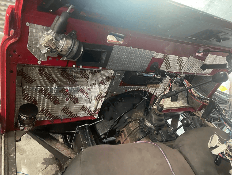
I have made some more progress with the interior and the dash. I have finished refitting the gearbox tunnel, fitted the footwell sound insulation which is form a later model. It has been trimmed to fit an lt77 but it still has a slight gap where it meets in the middle however most of this is covered by the fuse box so I can live with it. I have a new tunnel cover which was horribly priced (link) but it has been on my list to get one since befroe the fire. I will say the quality of it is poor and the fit is average at best but i am hoping with use it will settle a little.


I managed to get the steering guard refitted after swapping the PAS box, The arm on this box is clearly slightly different or sits lower on the splines than the old one so it was catching the bottom of the guard. After elongating the rear holes a little more than they already were it now sits correctly and does not catch the arm at any point.
I have made some more progress with the interior and the dash. I have finished refitting the gearbox tunnel, fitted the footwell sound insulation which is form a later model. It has been trimmed to fit an lt77 but it still has a slight gap where it meets in the middle however most of this is covered by the fuse box so I can live with it. I have a new tunnel cover which was horribly priced (link) but it has been on my list to get one since befroe the fire. I will say the quality of it is poor and the fit is average at best but i am hoping with use it will settle a little.
I have also made progress with the dash and interior wiring, I finally got the heater controls connected and adjusted up correctly. Interestingly the fan control cable run seems very tight but it is the one that came off the donor bulkhead so I assume it worked before. It has connected up and adjusted with no issues but there is not as much slack as in the heat control cable.
I have got all the wiring in place for the raptor dash console and hopefully over the weekend will fit the econoseal multi pin plugs to it allowing for panels to be removed with a single plug rather than disconnecting everything individually and then get the console fitted. This should then be the dash complete other than the speedo binnacle.

I have got all the wiring in place for the raptor dash console and hopefully over the weekend will fit the econoseal multi pin plugs to it allowing for panels to be removed with a single plug rather than disconnecting everything individually and then get the console fitted. This should then be the dash complete other than the speedo binnacle.
I have also completed what feels like a big milestone but in reality was not a big job and was just waiting on wiring to be completed. I have fitted (nearly completely) the passenger wing. I can now feed the loom to the front and connect up the heater ducting and snorkel. However I am struggling to tighten one fo the wing bolts. The second one form the top:

What tips and tricks do people have to tighten this up, it is in place and three quarters in but the wing intake and heater box get in the way and make it almost impossible to get a ratchet onto even with various UJ's and extensions. But other than that botl the wing is fitted.

What tips and tricks do people have to tighten this up, it is in place and three quarters in but the wing intake and heater box get in the way and make it almost impossible to get a ratchet onto even with various UJ's and extensions. But other than that botl the wing is fitted.
Hicap phill
Well-Known Member
- Posts
- 17,286
- Location
- Wiltshire
I used some really long extension bars or hand through the vent hole
I will try the vent hole again. I had given up with that and was trying to get up from the bottom.I used some really long extension bars or hand through the vent hole
Well going in from the vent hole was a non starter as the intake is in the way. I have ordered a 14mm flex head ratchet spanner (the size missing from my set) so will see if I can tighten it with that and if not will give up and not bother!
I have managed to get the drivers wing fitted that took a bit more persuasion than I was expecting but I am not too surprised. It was not the wing which was removed as that had been melted and this weeing had (still has but much better than it was) a fairly bad case of farmers wing. With the wings fitted I have been able to rung the wiring looms to the front corners and can now finish wiring in some of the extra controls at the front end like the fan control switch and the winch solenoid.

I also came across these outrigger mudflaps from Gwyn lewis (link) and though they were rather a good idea. Other than cutting them about an inch too short so ti doesnt fully cover the outrigger am I missing something or does my free piece of old conveyor belt do exactly the same job?

I have managed to get the drivers wing fitted that took a bit more persuasion than I was expecting but I am not too surprised. It was not the wing which was removed as that had been melted and this weeing had (still has but much better than it was) a fairly bad case of farmers wing. With the wings fitted I have been able to rung the wiring looms to the front corners and can now finish wiring in some of the extra controls at the front end like the fan control switch and the winch solenoid.
I also came across these outrigger mudflaps from Gwyn lewis (link) and though they were rather a good idea. Other than cutting them about an inch too short so ti doesnt fully cover the outrigger am I missing something or does my free piece of old conveyor belt do exactly the same job?
- Posts
- 5,082
I also came across these outrigger mudflaps from Gwyn lewis (link) and though they were rather a good idea. Other than cutting them about an inch too short so ti doesnt fully cover the outrigger am I missing something or does my free piece of old conveyor belt do exactly the same job? <snip>
Yours does the same job (at the end if the day) the advantage with the GL ones is that they come with some galvy brackets and all the bolts etc.
I have also managed to "fix" my voltmeter so that the raptor dash is now complete and ready to be fitted. I am just waiting for some heater boots for where the vent hose joins so I can refit the grey back panel and fully complete the dash.
I acquired another land rover voltmeter that has the glass smashed and the green bulb holder broken off the housing. The voltmeter itself however was working. Some time spent carefully prizing the bezel off allowed me to remove the broken glass and extract the voltmeter itself. I then had to very very carefully repeat the process on the voltmeter that came from @Hicap phill (once again many thanks) to ensure I did not break this glass. I then put the working voltmeter in the dial housing that had the green illumination housing enact, refitted the glass and then again very carefully re-clamped the bezel down using a small punch.
I am not sure how good the seal will be from re-clamping it. The rubber gasket was intact and refitted correctly but I ma not sure if it would be worth very carfully applying a small seam of sealant around the bezel ring where it has been bent back over to meet the body. What are peoples opinion?

Also looking at the voltmeter itself it is just a wire coil and some resistors unless I am missing something. What is likely to have failed in it to give the symptoms I had above and is it likely to be repairable or is it just not worth it?

I acquired another land rover voltmeter that has the glass smashed and the green bulb holder broken off the housing. The voltmeter itself however was working. Some time spent carefully prizing the bezel off allowed me to remove the broken glass and extract the voltmeter itself. I then had to very very carefully repeat the process on the voltmeter that came from @Hicap phill (once again many thanks) to ensure I did not break this glass. I then put the working voltmeter in the dial housing that had the green illumination housing enact, refitted the glass and then again very carefully re-clamped the bezel down using a small punch.
I am not sure how good the seal will be from re-clamping it. The rubber gasket was intact and refitted correctly but I ma not sure if it would be worth very carfully applying a small seam of sealant around the bezel ring where it has been bent back over to meet the body. What are peoples opinion?
Also looking at the voltmeter itself it is just a wire coil and some resistors unless I am missing something. What is likely to have failed in it to give the symptoms I had above and is it likely to be repairable or is it just not worth it?
That is reassuring. I was trying to work out if I had missed something special they did, but my piece of rubber belt with protect the footwell which is what I am primarily interested in.Yours does the same job (at the end if the day) the advantage with the GL ones is that they come with some galvy brackets and all the bolts etc.
View attachment 283556
Seaswood
Active Member
- Posts
- 242
- Location
- Falmouth New England
Those wing attachments are tricky a combination of extensions what ever can fit in there.
Sometimes it is helpful to walk away come back later with a new idea, let it cook overnight.
Sometimes it is helpful to walk away come back later with a new idea, let it cook overnight.
I have a dedicated thread here but will add it to this thread as well for completeness and to keep everything together.
I have now acquired a roof lining for my 110 rebuild (thread) and I am trying to work out if there is a benefit to be had from insulation the roof in either sound, thermal or a combination before fitting the roof lining. Previously I did not have any insulation and just had the hardtop roof and roof lining.
I have insulated the bulkhead, tunnel, and seat box with alubutyl sound deadening (link). And I know people have successfully thermally insulated the roof using camping mats (which I would be looking to use) but any closed cell foam will do the job.
I have a 110 hardtop so there is no sunroof and no alpine windows fitted it is just an expanse of flat tin with the internal strengthening ribs. Is there any benefit of either foam or alubutyl if I am also fitting a headlining?
If there is I assume a combination is better than either individually but my next question is does the alubutyl need full coverage or would a large panel in the middle of each section do the job before then covering in foam?
Similar threads
- Replies
- 7
- Views
- 681