- Posts
- 83,230
- Location
- Embasinga stocæ
Relay Basics:
 A relay is used to isolate one electrical circuit from another. It allows a low current control circuit to make or break an electrically isolated high current circuit path. One example where a relay is useful in car audio is in the power antenna or remote output of a head unit. We already said that the average remote lead can only handle about one half of an amp of current. If a circuit with a large amount of current must be controlled by the remote output lead of a head unit, a relay could be used to buffer the remote output from the head unit. The basic relay consists of a coil and a set of contacts. The most common relay coil is a length of magnet wire wrapped around a metal core. When voltage is applied to the coil, current passes through the wire and creates a magnetic field. This magnetic field pulls the contacts together and holds them there until the current flow in the coil has stopped. The diagram below shows the parts of a simple relay.
Relay Demo: Drag your mouse over the picture below. You'll see how the relay closes to allow current to flow through the bottom lamp when the coil is connected to the power source. You can see how current flows through either set of contacts depending on the position of the movable contact. If you have a slow connection, you may have to hold your mouse over the image until it loads completely. Since this page has a LOT of graphics, this will work best if you let the page load completely before using this demo. Clicking on the picture will bring the image to the top of the frame.
The table below shows just a fraction of the available relay configurations.
 This is a Single Pole Single Throw relay. Current will only flow through the contacts when the relay coil is energized.
 This is a Single Pole Double Throw relay. Current will flow between the movable contact and one fixed contact when the coil is DEenergized and between the movable contact and the alternate fixed contact when the relay coil is energized. The most commonly used relay in car audio, the Bosch relay, is a SPDT relay.
 This is a Double Pole Single Throw relay. When the relay coil is energized, two separate and electrically isolated sets of contacts are pulled down to make contact with their stationary counterparts. There is no complete circuit path when the relay is DEenergized.
 This relay is a Double Pole Double Throw relay. It operates like the SPDT relay but has twice as many contacts. There are two completely isolated sets of contacts.
 Yep! You guessed it. This is a 4Pole Double Throw relay. It operates like the SPDT relay but it has 4 sets of isolated contacts. Relay Specifications: There are two specifications that you must consider when selecting a relay for use in an automobile, the coil voltage and the current carrying capability of contacts. The coil voltage for relays used in automobiles is ~12 volts. This means that if you apply 12 volts to the coil, it will pull in and stay there until the applied voltage is removed from the coil. The current rating on relay contacts tells how much current can be passed through the contacts without damage to the contacts. Some relays have different current ratings for the NC contacts (which are held together by spring tension) and the NO contacts (which are held together by the electromagnet). If you need to pass significant current through the NC contacts, you may want to check the manufacturers specifications for the relay.
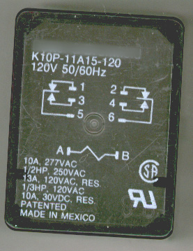
The relay pictured above has a coil designed to accept 120 VAC at 50 to 60hz. If you look at the specifications on the relay cover below, you will see that the coil was designed to operate on 120 volts A.C. There are relays designed for use with 5vdc, 12vdc, 12vac, 24vdc, 24vac. Make sure that you check the relay's specifications when using a relay that you're not familiar with.
The Famous Bosch Relay
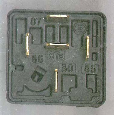
Bottom View: The most commonly used relay in car audio and security is the Bosch relay. The picture below is the bottom of a Bosch relay. Take note of the markings (85, 86, 87, 87a, & 30) near the terminals.
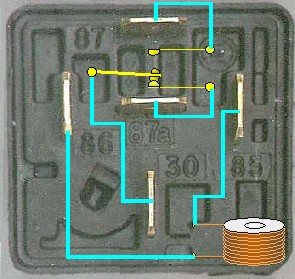
Internal Workings of Bosch relay: The following diagram shows what those external terminals are connected to on the inside of the relay. When there is no difference of potential (voltage) across terminals 85 and 86 (the coil), the relay's movable contact (connected to terminal 30) is held, by spring tension, against the electrical contact which is connected to terminal 87a (the normally closed contact). In other words, when no voltage is applied the the relay coil, terminal 87a is connected to terminal 30. When 12 volts is applied to the relay coil (terminals 85 and 86), the movable contact (connected to terminal 30) is pulled down/in by the electromagnet (coil) so that it physically contacts the electrical contact which is connected to terminal 87. Again, in other words, if battery voltage is applied to the relay coil (terminals 85 and 86) terminal 30 will be connected to terminal 87. The red dashed line shows the path in which electrical current flows from/through terminal 30 to the contact of terminal 87a when the relay coil is NOT energized.
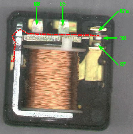
Remember that the relay coil has to have a difference of potential between terminals 85 and 86 in order for the coil to pull the armature in/down. This means that you may apply battery voltage to either terminal 85 OR 86 and then ground the OTHER terminal. The positive battery voltage OR the ground connection may be broken to make relay switch terminals (87 to 87a).
Quenching Diodes: Anytime that a relay coil is driven by a circuit that is not specifically designed to drive a relay, you should use a quenching/suppression diode connected in parallel with the relay coil. The diagram below will show the connection of the diode. Initially, you may think the diode serves no purpose because the voltage applied to the relay cannot pass through the diode. This is true when the relay is energized. The diode comes into play when the power source is removed from the relay coil. When power is applied to the relay coil, a magnetic field is created and energy is stored in the coil. When power is removed, the magnetic field collapses causing a reverse voltage to be generated (it's called inductive kickback or back EMF). The back EMF can easily reach 200 volts. The diode will absorb the reverse voltage spike. This voltage, if not absorbed by the diode, will cause premature failure of switch contacts and may cause the failure of power switching transistors. You can use virtually any type of rectifier or switching diode (i.e. 1N4001, 1N4002, 1N400x... or Radio Shack part #s 276-1101, 276-1102, 276-1103, 276-1104).
Voltage Graphs: The following diagram shows 2 different voltage graphs. The top graph shows how the parallel diode quenches the reverse voltage. The bottom graph shows the unsuppressed voltage. This voltage can damage low voltage transistors and switches. You can right click on the diagram to zoom in on the graphs.
Note: Earlier I said that you energize the relay by applying positive voltage to either 85 OR 86 and grounding the remaining terminal. The only thing that changes when using the quenching diode is the fact that the positive terminal and the striped end of the diode must be together. If the positive control lead is connected to the diode's anode (unstriped end of diode). There will effectively be a short circuit to ground possibly causing damage to the control circuit (if the control circuit is not properly fused). A 1 amp fuse will carry more than enough current to energize the relay's coil.
Relays with Internal Suppression Circuits: There are some relays with internal suppression circuits which make the external diode unnecessary. The suppression circuit is generally a resistor or a diode parallel to the relay coil. The relays with a diode suppressor will have polarity sensitive coil connections. This means that the proper relay coil terminal (the positive terminal) must have the positive voltage applied to it. If the relay is connected improperly, the relay may be damaged or in some cases it simply won't operate.
Pull in Voltage: The pull in voltage is the minimum voltage required for the relay coil to pull the contacts (30 and 87 on the Bosch relay) together. The pull in voltage is about 8 volts for a typical Bosch relay.
Drop out Voltage: The drop out voltage is the voltage at which the energized coil will release the movable contact. The drop out voltage is somewhere between 1 and 5 volts for a bosch relay.
Coil Resistance: In a DC relay coil, the coil resistance determines the current flow through the coil. The current draw by the coil of a bosch relay is ~0.160 amps (~75 ohm coil). In an AC relay coil, the resistance does not solely determine the current flow through the coil because the coil has inductance. The inductive reactance along with the DC resistance work together to limit the current flow through the coil.
Relay Demo: Drag your mouse over the picture below. You'll see how the relay closes to allow current to flow through the bottom lamp when the coil is connected to the power source. You can see how current flows through either set of contacts depending on the position of the movable contact. If you have a slow connection, you may have to hold your mouse over the image until it loads completely. Since this page has a LOT of graphics, this will work best if you let the page load completely before using this demo. Clicking on the picture will bring the image to the top of the frame.
The table below shows just a fraction of the available relay configurations.
The relay pictured above has a coil designed to accept 120 VAC at 50 to 60hz. If you look at the specifications on the relay cover below, you will see that the coil was designed to operate on 120 volts A.C. There are relays designed for use with 5vdc, 12vdc, 12vac, 24vdc, 24vac. Make sure that you check the relay's specifications when using a relay that you're not familiar with.
The Famous Bosch Relay
Bottom View: The most commonly used relay in car audio and security is the Bosch relay. The picture below is the bottom of a Bosch relay. Take note of the markings (85, 86, 87, 87a, & 30) near the terminals.
Internal Workings of Bosch relay: The following diagram shows what those external terminals are connected to on the inside of the relay. When there is no difference of potential (voltage) across terminals 85 and 86 (the coil), the relay's movable contact (connected to terminal 30) is held, by spring tension, against the electrical contact which is connected to terminal 87a (the normally closed contact). In other words, when no voltage is applied the the relay coil, terminal 87a is connected to terminal 30. When 12 volts is applied to the relay coil (terminals 85 and 86), the movable contact (connected to terminal 30) is pulled down/in by the electromagnet (coil) so that it physically contacts the electrical contact which is connected to terminal 87. Again, in other words, if battery voltage is applied to the relay coil (terminals 85 and 86) terminal 30 will be connected to terminal 87. The red dashed line shows the path in which electrical current flows from/through terminal 30 to the contact of terminal 87a when the relay coil is NOT energized.
Remember that the relay coil has to have a difference of potential between terminals 85 and 86 in order for the coil to pull the armature in/down. This means that you may apply battery voltage to either terminal 85 OR 86 and then ground the OTHER terminal. The positive battery voltage OR the ground connection may be broken to make relay switch terminals (87 to 87a).
Quenching Diodes: Anytime that a relay coil is driven by a circuit that is not specifically designed to drive a relay, you should use a quenching/suppression diode connected in parallel with the relay coil. The diagram below will show the connection of the diode. Initially, you may think the diode serves no purpose because the voltage applied to the relay cannot pass through the diode. This is true when the relay is energized. The diode comes into play when the power source is removed from the relay coil. When power is applied to the relay coil, a magnetic field is created and energy is stored in the coil. When power is removed, the magnetic field collapses causing a reverse voltage to be generated (it's called inductive kickback or back EMF). The back EMF can easily reach 200 volts. The diode will absorb the reverse voltage spike. This voltage, if not absorbed by the diode, will cause premature failure of switch contacts and may cause the failure of power switching transistors. You can use virtually any type of rectifier or switching diode (i.e. 1N4001, 1N4002, 1N400x... or Radio Shack part #s 276-1101, 276-1102, 276-1103, 276-1104).
Voltage Graphs: The following diagram shows 2 different voltage graphs. The top graph shows how the parallel diode quenches the reverse voltage. The bottom graph shows the unsuppressed voltage. This voltage can damage low voltage transistors and switches. You can right click on the diagram to zoom in on the graphs.
Note: Earlier I said that you energize the relay by applying positive voltage to either 85 OR 86 and grounding the remaining terminal. The only thing that changes when using the quenching diode is the fact that the positive terminal and the striped end of the diode must be together. If the positive control lead is connected to the diode's anode (unstriped end of diode). There will effectively be a short circuit to ground possibly causing damage to the control circuit (if the control circuit is not properly fused). A 1 amp fuse will carry more than enough current to energize the relay's coil.
Relays with Internal Suppression Circuits: There are some relays with internal suppression circuits which make the external diode unnecessary. The suppression circuit is generally a resistor or a diode parallel to the relay coil. The relays with a diode suppressor will have polarity sensitive coil connections. This means that the proper relay coil terminal (the positive terminal) must have the positive voltage applied to it. If the relay is connected improperly, the relay may be damaged or in some cases it simply won't operate.
Pull in Voltage: The pull in voltage is the minimum voltage required for the relay coil to pull the contacts (30 and 87 on the Bosch relay) together. The pull in voltage is about 8 volts for a typical Bosch relay.
Drop out Voltage: The drop out voltage is the voltage at which the energized coil will release the movable contact. The drop out voltage is somewhere between 1 and 5 volts for a bosch relay.
Coil Resistance: In a DC relay coil, the coil resistance determines the current flow through the coil. The current draw by the coil of a bosch relay is ~0.160 amps (~75 ohm coil). In an AC relay coil, the resistance does not solely determine the current flow through the coil because the coil has inductance. The inductive reactance along with the DC resistance work together to limit the current flow through the coil.