Henry_b
Think outside, no box required.
- Posts
- 15,558
- Location
- somewhere else
Don't know how comprehensible this'll be so bear with me and read it slowly ")
After this exercise you can say i'm an l322 fan
#1 Building the heads..
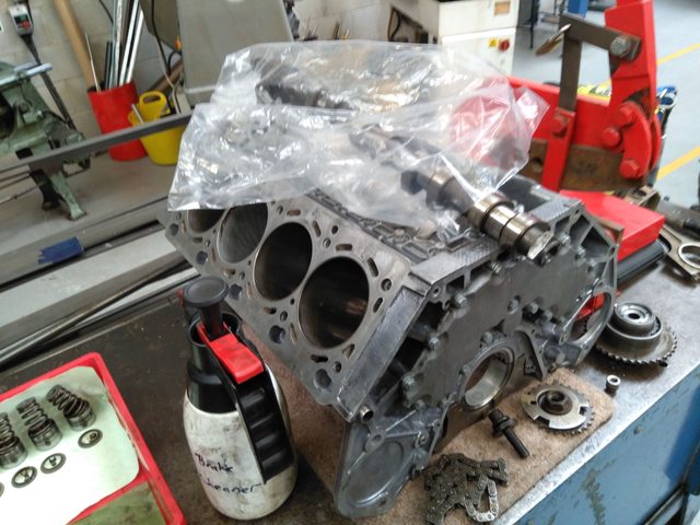
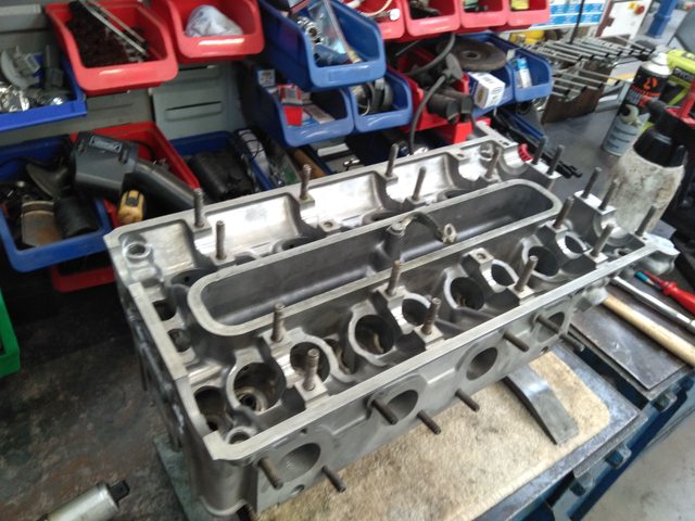
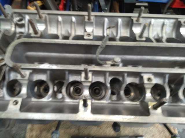
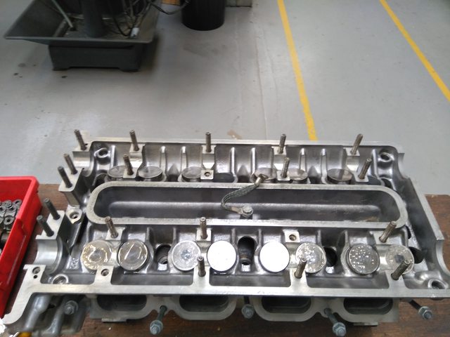
The cylinder heads on this engine were cleaned and checked for any warping before building..
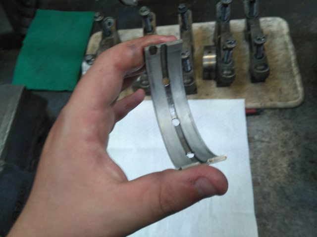
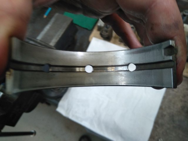
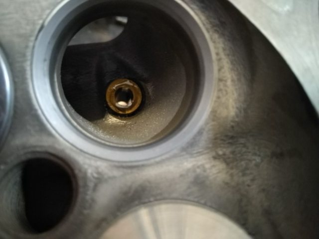
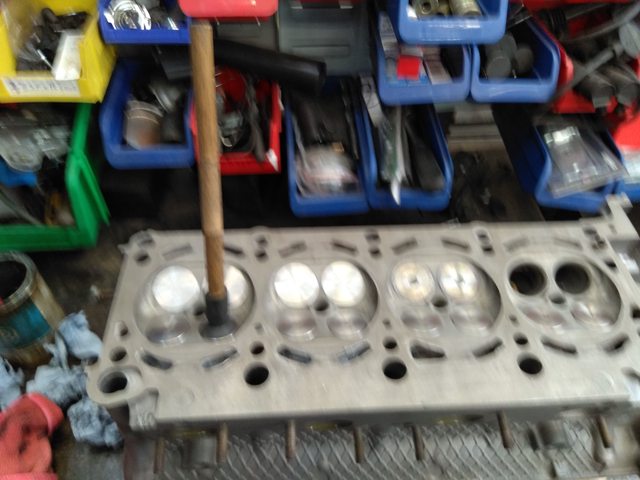
The bare head.
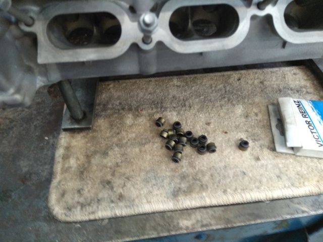
New stem seals below, these are easy as pie to fit just place over lip aove the valve guide and give 'em a tap.
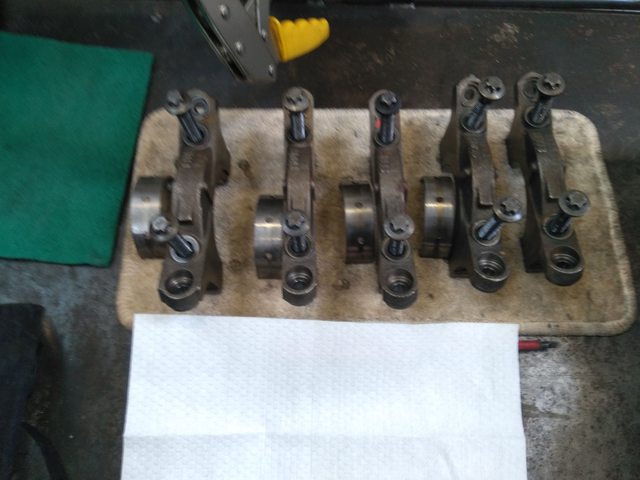
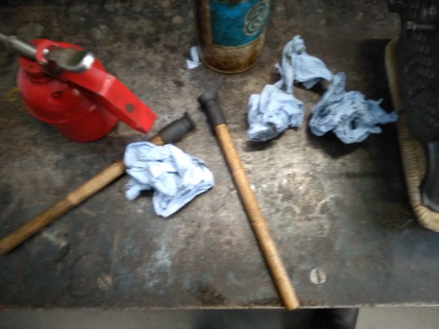
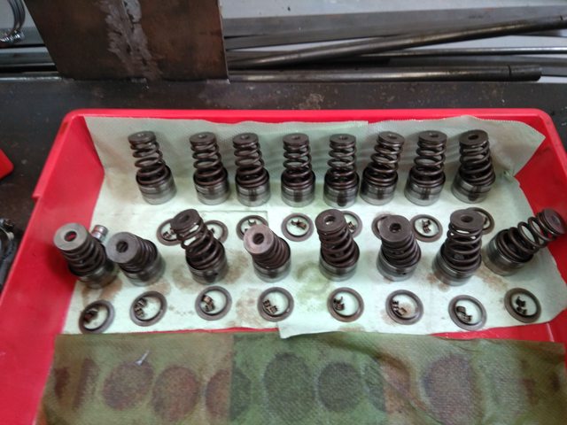
Below is all the components that have to be assembled on to the head.
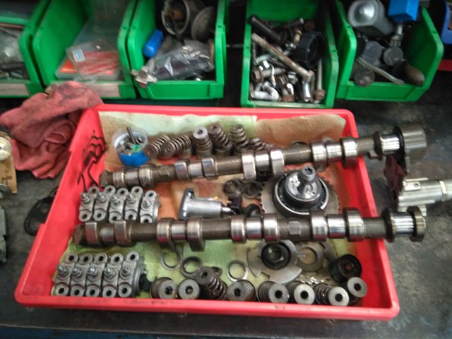
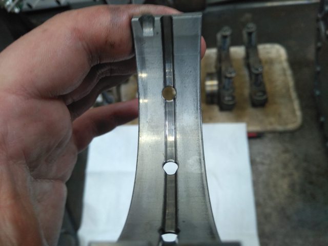
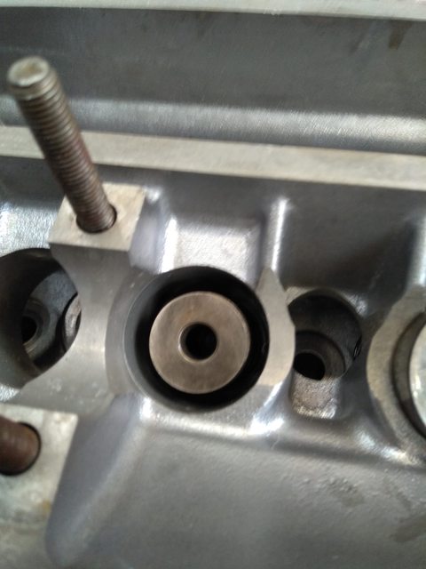
The Tappets on this engine, naturally were empty of all the oil. To prevent any rattling and undue wear i managed to disassemble and re prime them.
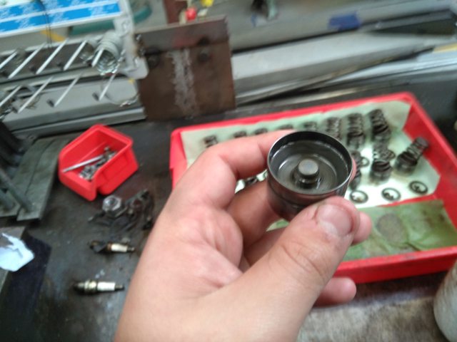
In the picture above you can see the small plunger/piston in the middle, to reprime them you have to pull this out.
A small pair of vice grips will see them removed, once the piston is out you have to pull that apart, aswell.
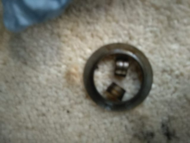
Inside this little plunger is a small spring and check valve, don't lose the spring!!
Clean the tappet bore and little plunger/piston with brake cleaner or iso alcohol to ensure all sludge and varnish is removed.
The little plunger should be half filled with oil which is a minuscule amount, and the bore where it sits in the tappet should also be filled, once this is done refit the little plunger to the tappet.
At this point the plunger should be almost solid in the tappet with no movement.
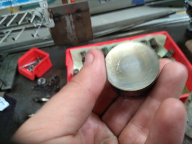
Also at this point make sure the face of the tappet where the cam lose hits is in good condition.
2# Valves.
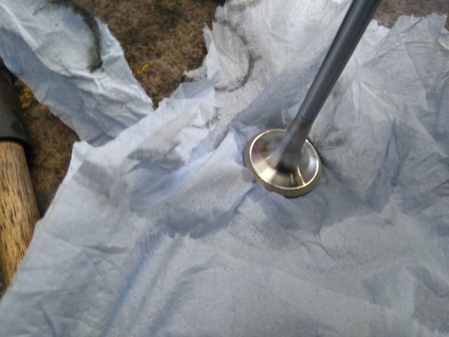
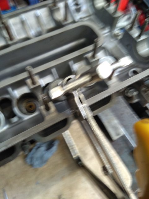
In this particular instance new valves were acquired, before fitment they had to be ground to the valve seats to ensure a good seal!
The compound i used was a rather unaggressive type, it only took 2mins per valve so clearly it was the right stuff..
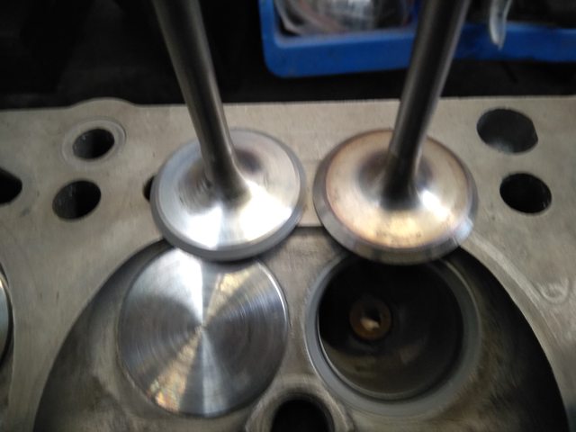
Once all the valves were properly ground to the head the valve springs have to be fitted
These little Bástards are taper'd and the taper goes towards the valve, these are right pains to fit so make sure your parkinsons doesn't flare up when you try to fit them like mine did.
The spring compressor in this case was rather unwieldy!!
And fitted, that only took way longer than it should of!!
After double checking everything, fit the primed tappets onto the valve springs, I oriented the oil feed hole in the tappets to the one in the block to ensure maximum oil flow during its first initial start.
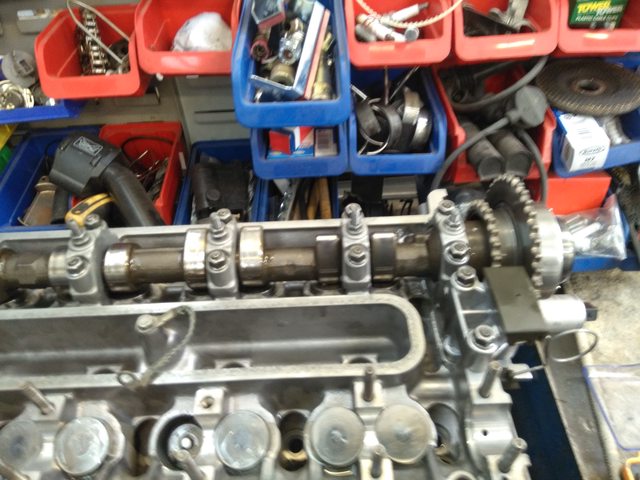
Then fit the cam, I coated the cam bearings in assembly lubricant before fitting, for anyone wondering the securing bolts are 11mm.
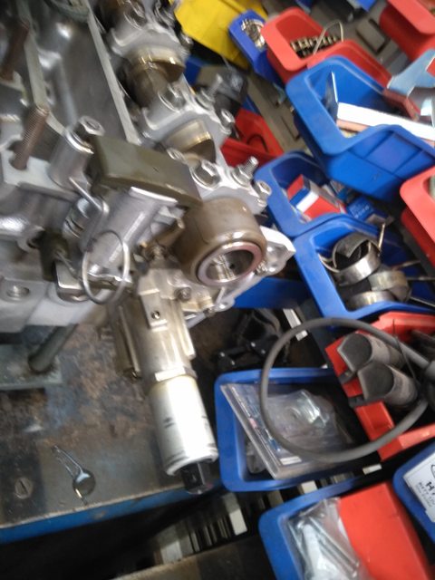
Next its the vanos which is a pain in the hoop to set up.
Underneath this unit is a gasket for the love of god make sure it isn't bent and also fit a new one, don't reuse the old one, the securing bolts were 13mm
A new cam chain tensioner was also fitted.
Below is the sprocket, this was checked and is in good order.
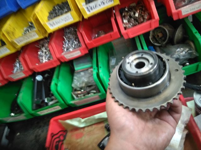
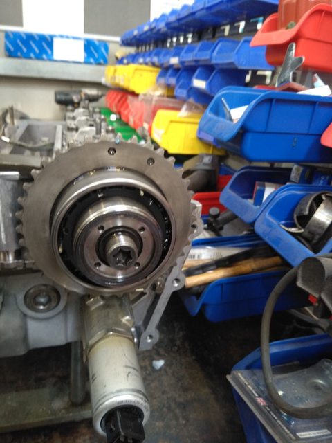
And fitted
Don't be an idiot the securing bolt is left hand thread, what a dope i am..
Next
Tighten down the spocket retaining bolt "left hand thread" this is to seat the spocket,
#2 loosen the bolts back off 1/8 of a turn this allows them to rotate freely which is needed to set up the timing.
#3 Fit the cam chain and unlock the cam chain tensioner, compress the tensioner and pull out the clip from the locking holes, this is for all the tensioner btw,
#4 Install crankshaft chain locking tool
1 Thread the tool's spindle nut fully into tool block
2 Mount the tool block with upper timing long bolt at the top and the short one at the bottom
3 Align block with head to facilitate the insersion of the bolt
4 Lightly tighten the bolts.
5 Tighten tensioner tool spindle to press against chain rail guide and tension crankshaft chain
6 Check to make sure the crankshaft chain is positioned on chain rail guides
7 Tighten until it become too difficult to further tighten.
8 The amount off chain tightening and thread showing will depend on age and stretch of the chain.
9 Make sure the chain is tight in all segemrnt
10 Check and align camshafts and camsgaft locking blocks as needed.
11 press down on the cams while rocking back and forward to fully seat block on head surface
12 loosen and retghten locking blocks bolts as needed to make sure the block mounts correctly.
13 Fully retard bank 1 and 2 cam timing, for each vanos perform the below..
1 Connect Ohm meter to positive lead to one of the vanos test pins
2 and connect negative lead to intake camshafts first beafing cam stud
3 Turn on the OHM meter
4 Install vanos tool on centre vanos shaft, insert pins into correct vanos shift pin holes
5 Turn vanos shaft counter clockwise until end adjustment position is reached
6 Vanos internal piston will connect with vanos test pins when fully retarded and cause a short reading 0 ohms
7 When ratchet pressure is released ohm reading can shift to open circuit " Infinite ohm" this is ok.
Locking of engine timing.
erform following two steps in two passes. First pass lightly tighten vanos and exhaust sprocket mounting bolts to fix timing. Second pass fully tighten vanos and exhaust sprocket mounting bolts.
Mounting bolt tightening torque values are high and set timing can be disturbed in tightening process. Two pass tightening allows fixing set timing at first pass then fully tightening at second when timing can’t be disturbed.
Tighten bank 1 & 2 vanos mounting bolt. For each vanos perform following.
Tighten bank 2 then bank 1. This assures any chain looseness it drawn to chain tensioner.
Counter hold intake camshaft and fully tighten vanos mounting bolt, first pass 20 Nm (15 ft-lb), second pass 110 Nm (81 ft-lb); left hand thread (T55 torx bit socket 3/8″ w/ 1/2” to 3/8” socket adapter / 1/2″ torque wrench, 27mm open wrench).
Make sure tool inserts fully into vanos bolt head (T55 torx bit 3/8”).
Ensure Intake camshaft is counter held by locking block. But do not rely on this alone as camshaft can be damaged. Further counter hold camshaft at camshaft hex.
Check and realign camshafts and camshaft locking blocks as necessary.
Tighten bank 1 & 2 exhaust sprocket mounting bolt. For each exhaust sprocket perform following.
Tighten bank 2 then bank 1. This assures any chain looseness it drawn to chain tensioner.
Counter hold exhaust camshaft and fully tighten exhaust sprocket mounting bolt, first pass 20 Nm (15 ft-lb), second pass 125 Nm (92 ft-lb); left hand thread (T55 torx bit socket 3/8″ w/ 1/2” to 3/8” socket adapter / 1/2″ torque wrench, 27mm open wrench).
Check to Verify tool inserts fully into sprocket bolt head (T55 torx bit 3/8”).
Make sure: Exhaust camshaft is counter held by locking block. But do not rely on this alone as camshaft can be damaged. Further counter hold camshaft at camshaft hex.
Check and realign camshafts and camshaft locking blocks as necessary.
Mount bank 1 & 2 intake camshaft timing wheel. For each timing wheel perform following.
Mount timing wheel on vanos mounting bolt and install mounting nut; left hand thread.
Timing wheel rear has center protruding neck which mounts into vanos.
Do not tighten mounting nut at this time.
Rotate timing wheel to position reference hole approximately.
Install bank 1 & 2 timing wheel positioning tool. For each timing wheel perform following.
Mount corresponding timing wheel positioning tool at timing cover head surface and insert tool pin in timing wheel hole. Rotate timing wheel as needed for pin/hole alignment.
Mount positioning tool with upper timing cover long bolt at top and short bolt at bottom. Rest positioning tool top bracket on head top to align positioning tool and facilitate bolt insertion. Do not fully tighten bolts at this time.
Precisely align positioning tool by aligning top bracket onto head top surface. Lightly tighten mounting bolts (10mm socket 3/8” / 3/8” extension).
Tighten bank 1 & 2 timing wheel mounting nut. For each timing wheel perform following.
Fully tighten timing wheel mounting nut, 40 Nm (29.5 ft-lb); left hand thread (24mm socket 1/2″ / 1/2″ torque wrench).
Remove bank 1 & 2 timing wheel positioning tool mounting bolts and remove positioning tools (10mm socket 3/8” / 3/8” extension).
Loosen chain tensioning tool spindle (8mm socket 1/4″ / fingers).
Remove tool block 2 mounting bolts and remove chain tensioning tool (10mm socket 3/8” / 3/8” extension).
Remove tool spindle nut from tool block.
Unlocking of camshafts
Remove bank 1 & 2 camshaft locking blocks. For each camshaft set perform following.
Loosen locking blocks matting bolt (6mm hex bit socket 3/8” / 3/8” ratchet).
Dislodge and remove locking blocks.
After this exercise you can say i'm an l322 fan
#1 Building the heads..
The cylinder heads on this engine were cleaned and checked for any warping before building..
The bare head.
New stem seals below, these are easy as pie to fit just place over lip aove the valve guide and give 'em a tap.
Below is all the components that have to be assembled on to the head.
The Tappets on this engine, naturally were empty of all the oil. To prevent any rattling and undue wear i managed to disassemble and re prime them.
In the picture above you can see the small plunger/piston in the middle, to reprime them you have to pull this out.
A small pair of vice grips will see them removed, once the piston is out you have to pull that apart, aswell.
Inside this little plunger is a small spring and check valve, don't lose the spring!!
Clean the tappet bore and little plunger/piston with brake cleaner or iso alcohol to ensure all sludge and varnish is removed.
The little plunger should be half filled with oil which is a minuscule amount, and the bore where it sits in the tappet should also be filled, once this is done refit the little plunger to the tappet.
At this point the plunger should be almost solid in the tappet with no movement.
Also at this point make sure the face of the tappet where the cam lose hits is in good condition.
2# Valves.
In this particular instance new valves were acquired, before fitment they had to be ground to the valve seats to ensure a good seal!
The compound i used was a rather unaggressive type, it only took 2mins per valve so clearly it was the right stuff..
Once all the valves were properly ground to the head the valve springs have to be fitted
These little Bástards are taper'd and the taper goes towards the valve, these are right pains to fit so make sure your parkinsons doesn't flare up when you try to fit them like mine did.
The spring compressor in this case was rather unwieldy!!
And fitted, that only took way longer than it should of!!
After double checking everything, fit the primed tappets onto the valve springs, I oriented the oil feed hole in the tappets to the one in the block to ensure maximum oil flow during its first initial start.
Then fit the cam, I coated the cam bearings in assembly lubricant before fitting, for anyone wondering the securing bolts are 11mm.
Next its the vanos which is a pain in the hoop to set up.
Underneath this unit is a gasket for the love of god make sure it isn't bent and also fit a new one, don't reuse the old one, the securing bolts were 13mm
A new cam chain tensioner was also fitted.
Below is the sprocket, this was checked and is in good order.
And fitted
Don't be an idiot the securing bolt is left hand thread, what a dope i am..
Next
Tighten down the spocket retaining bolt "left hand thread" this is to seat the spocket,
#2 loosen the bolts back off 1/8 of a turn this allows them to rotate freely which is needed to set up the timing.
#3 Fit the cam chain and unlock the cam chain tensioner, compress the tensioner and pull out the clip from the locking holes, this is for all the tensioner btw,
#4 Install crankshaft chain locking tool
1 Thread the tool's spindle nut fully into tool block
2 Mount the tool block with upper timing long bolt at the top and the short one at the bottom
3 Align block with head to facilitate the insersion of the bolt
4 Lightly tighten the bolts.
5 Tighten tensioner tool spindle to press against chain rail guide and tension crankshaft chain
6 Check to make sure the crankshaft chain is positioned on chain rail guides
7 Tighten until it become too difficult to further tighten.
8 The amount off chain tightening and thread showing will depend on age and stretch of the chain.
9 Make sure the chain is tight in all segemrnt
10 Check and align camshafts and camsgaft locking blocks as needed.
11 press down on the cams while rocking back and forward to fully seat block on head surface
12 loosen and retghten locking blocks bolts as needed to make sure the block mounts correctly.
13 Fully retard bank 1 and 2 cam timing, for each vanos perform the below..
1 Connect Ohm meter to positive lead to one of the vanos test pins
2 and connect negative lead to intake camshafts first beafing cam stud
3 Turn on the OHM meter
4 Install vanos tool on centre vanos shaft, insert pins into correct vanos shift pin holes
5 Turn vanos shaft counter clockwise until end adjustment position is reached
6 Vanos internal piston will connect with vanos test pins when fully retarded and cause a short reading 0 ohms
7 When ratchet pressure is released ohm reading can shift to open circuit " Infinite ohm" this is ok.
Locking of engine timing.
erform following two steps in two passes. First pass lightly tighten vanos and exhaust sprocket mounting bolts to fix timing. Second pass fully tighten vanos and exhaust sprocket mounting bolts.
Mounting bolt tightening torque values are high and set timing can be disturbed in tightening process. Two pass tightening allows fixing set timing at first pass then fully tightening at second when timing can’t be disturbed.
Tighten bank 1 & 2 vanos mounting bolt. For each vanos perform following.
Tighten bank 2 then bank 1. This assures any chain looseness it drawn to chain tensioner.
Counter hold intake camshaft and fully tighten vanos mounting bolt, first pass 20 Nm (15 ft-lb), second pass 110 Nm (81 ft-lb); left hand thread (T55 torx bit socket 3/8″ w/ 1/2” to 3/8” socket adapter / 1/2″ torque wrench, 27mm open wrench).
Make sure tool inserts fully into vanos bolt head (T55 torx bit 3/8”).
Ensure Intake camshaft is counter held by locking block. But do not rely on this alone as camshaft can be damaged. Further counter hold camshaft at camshaft hex.
Check and realign camshafts and camshaft locking blocks as necessary.
Tighten bank 1 & 2 exhaust sprocket mounting bolt. For each exhaust sprocket perform following.
Tighten bank 2 then bank 1. This assures any chain looseness it drawn to chain tensioner.
Counter hold exhaust camshaft and fully tighten exhaust sprocket mounting bolt, first pass 20 Nm (15 ft-lb), second pass 125 Nm (92 ft-lb); left hand thread (T55 torx bit socket 3/8″ w/ 1/2” to 3/8” socket adapter / 1/2″ torque wrench, 27mm open wrench).
Check to Verify tool inserts fully into sprocket bolt head (T55 torx bit 3/8”).
Make sure: Exhaust camshaft is counter held by locking block. But do not rely on this alone as camshaft can be damaged. Further counter hold camshaft at camshaft hex.
Check and realign camshafts and camshaft locking blocks as necessary.
Mount bank 1 & 2 intake camshaft timing wheel. For each timing wheel perform following.
Mount timing wheel on vanos mounting bolt and install mounting nut; left hand thread.
Timing wheel rear has center protruding neck which mounts into vanos.
Do not tighten mounting nut at this time.
Rotate timing wheel to position reference hole approximately.
Install bank 1 & 2 timing wheel positioning tool. For each timing wheel perform following.
Mount corresponding timing wheel positioning tool at timing cover head surface and insert tool pin in timing wheel hole. Rotate timing wheel as needed for pin/hole alignment.
Mount positioning tool with upper timing cover long bolt at top and short bolt at bottom. Rest positioning tool top bracket on head top to align positioning tool and facilitate bolt insertion. Do not fully tighten bolts at this time.
Precisely align positioning tool by aligning top bracket onto head top surface. Lightly tighten mounting bolts (10mm socket 3/8” / 3/8” extension).
Tighten bank 1 & 2 timing wheel mounting nut. For each timing wheel perform following.
Fully tighten timing wheel mounting nut, 40 Nm (29.5 ft-lb); left hand thread (24mm socket 1/2″ / 1/2″ torque wrench).
Remove bank 1 & 2 timing wheel positioning tool mounting bolts and remove positioning tools (10mm socket 3/8” / 3/8” extension).
Loosen chain tensioning tool spindle (8mm socket 1/4″ / fingers).
Remove tool block 2 mounting bolts and remove chain tensioning tool (10mm socket 3/8” / 3/8” extension).
Remove tool spindle nut from tool block.
Unlocking of camshafts
Remove bank 1 & 2 camshaft locking blocks. For each camshaft set perform following.
Loosen locking blocks matting bolt (6mm hex bit socket 3/8” / 3/8” ratchet).
Dislodge and remove locking blocks.
Last edited: