Freelander Project IV (Bertie)

This site contains affiliate links for which LandyZone may be compensated if you make a purchase.
So how does my Bell recon one fit in to your views on this?
They have an excellent reputation for doing it right so I can only presume they cut the end off, clean all the disks and make a better job than I ever could of welding it back together. Then through experience and experimenting they know exactly what fluid and how much of it to put back in.
If i had half a brain I would have gone with a Bell unit but I'm to stupid and too tight so end up giving myself a load of extra work.
They fitted a new set of bearings for me - they do it so quick and easy - my old bearing at the front prop end of the VCU needed the prop off to get it off!!
TBH Alibro it was worth the trip just to get their opinion on the existing VCU. Don't forget I have 150K miles on the clock so diagnostic words of wisdom is a boon. I even took the IRD oil with me for them to check and the swarf that was on the magnetic drain plug. But because even they could not shift the front prop it was even more worthwhile making the trip. I would have paid a King's ransom just to get that little bugger off.
Me gads, !:eek: I would have paid a king's ransom to get Alibro off me too ? or p am I missing the point ???? :D
 
Spent a little while tonight pouring in white spirit cranking the VCU round and pouring it out. Not the best fun in the world but beats cleaning 50 odd disks and the VCU before welding, grinding, rewelding cause my welding is crap and grinding again. Will do it again tomorrow for a while and see what the fluid comes out like. At the minute it is still very yucky.
A pic of the VCU in the vice and my patented turning system.
20160828_203257_zpsjpeahijm.jpg

On another topic spot the problem from this pic.
20160828_210611_zpsnpivxuxf.jpg

Yip the car was being driven with a broken wheel stud. :eek:
To add to this I was suspicious so had a wee check and the alloys don't have a spigot ring so they aren't being supported by the hub. Add to that the previous owner had copper slip between the wheel face and the hub and the only thing supporting the car is the strength of the wheel studs.
Death trap or what?
I'm all for a wee bit of copper slip around the spigot ring to stop alloys seizing but put it on the wheel face and you no longer have any friction contributing to holding the wheels on. If you accelerate or brake hard the studs take the full twisting force of the torque developed, maybe not a serious problem in a Freelander but on a more powerful car it could be.
Anyway I wanted to ask if anyone has any experience of buying wheel studs? They range in price from £8.70 for 5 aftermarket ones to £25 for 5. Obviously I'm going to change all 5 given the alloys not having spigot rings.
 
Last edited:
On another topic spot the problem from this pic.

Yip the car was being driven with a broken wheel stud. :eek:
To add to this I was suspicious so had a wee check and the alloys don't have a spigot ring so they aren't being supported by the hub.
Anyway I wanted to ask if anyone has any experience of buying wheel studs?

Over the years I have had a stud that lost its grip in the hub, broken ones (one done by me and ones like you) and ones I have stripped. I have changed a good few and I have to say I view removing nuts (possibly done by Kwikfit types) for the first time on a new acquisition with REAL trepidation. When I have to use a three foot breaker bar or when they groan and creak when being undone I get really anxious. As a result of my experiences I never overdo the tightening.

I would have thought that 5 lugs would be pretty strong.

Is that wheel hub going to clean up well A? I have to say I am really impressed with the overall great condition of my 16 year old. Maybe that is because most of it has had to be replaced over the years.:D:D

Because I get cars from around the 1990s I am used to really decaying stuff like front brake backing plates dissolving into rust when I touch them and so on but the one thing that might make me keep this motor more than owt else is the really good condition it is in especially for its age.
 
It's well known that tyre monkey's regularly over tighten wheel nuts with their windy guns and like you I cringe when taking them off. Some people put copper slip on wheel studs but that can lead to over stressed studs if your not careful as it's easier to over tighten them.
5 studs are strong but they should only be holding the wheel on the hub, not carrying the weight of the whole car.
The hub cleaned up pretty well and still has around 1mm of life left (measured inside diameter) so now it is painted it should be fine.
 
The hub cleaned up pretty well and still has around 1mm of life left (measured inside diameter) so now it is painted it should be fine.
I had an LJ80 back in the day and though I may be wrong (memory is not doing well looking back roughly 30 years) I think the rear hub - don't remember the front at all - had just a flat drum.
I paint drums with gold Hammerite once I have had at it with a welders chip hammer
Black wheels WMF.jpg
, bastard file and rotary brush.
 
Last two evenings I've been trying to sort out the cuts and adjustments required to the front chassis rails for my 50mm lift kit.
What a pain!
Here are my pearls of wisdom/stupidity/experience (delete as appropriate)
First if unless you really really need that extra 10mm then don't bother. Buy the 40mm kit instead and you will still need to cut some metal but not (so I'm told) the chassis rail.

******* Since writing this DieselDo suggested you can lessen the cutting required by swapping the steering arms. This will leave locking bolts on the track rod ends at the rear instead of the front which would help a lot. Also you can grind off a knob on the TRE to help a little more. This will help reduce the hammering and cutting a little but only if you do it before fitting the lift kit. I had already got the chassis arms adjusted for the TRE's before swapping the arms and now need to make more adjustments as the bolts now foul in a different spot. :(

OK, a quick update on how to swap the steering arms if you decide to do that. Note this was done on a TD4 with terrible access to the steering arm bolts. I did it from above but others have suggested it can be done through the wheel arch.

Tools required
14mm spanner. If you have the correct torx socket and enough space to get at it then life will be much easier for you.
Short(ish) length of pipe that fits over the spanner
Normal tools to remove track rod ends.
Loctite

1. Turn steering to move the rack to a point where you can get access to it.
2. Reach into the back of the engine bay and fit your 14mm spanner over the torx bolts, put the pipe over the spanner and start the process of loosening the bolt a 1/4 turn at a time.
3. Repeat many many times. No it doesn't loosen up or get any easier as it is held in with locktite. :(
4. Loosen both bolts at the same time and remove.
5. Remove track rod ends as described below. Take them to your grinder and carefully remove the nodule beside the bolt.
6. Swap the arms around and hesitate for a second as you see the TRE's are now upside down. Then laugh at your stupidity and remember they are screwed on and can be easily turned. :oops:
7. Using loctite refit the arms to the steering rack and tighten them up. I found the first one easy to get the bolt started but the second was a right pig. I found it helped to have the first one fairly tight.
Refit the TRE temporarily as described below and follow procedure for measuring, cutting and hammering.

Tools required
Long breaker bar
Hex socket set. (don't even think about doing it with a 12 point set)
Torque wrench
Big hammer, preferably ball pein.
Grinder
5mm Good quality allan key
Spanner set
Ball joint splitter

Spare parts required (probably)
Track rod ends
Drop links


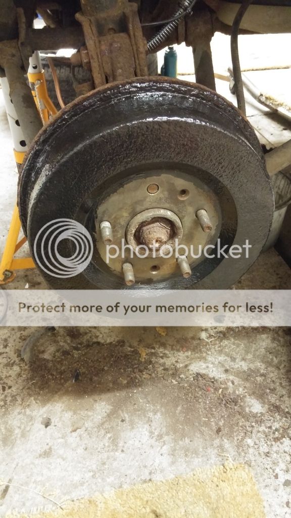
1. Jack the car up and remove both front wheels
2. Turn the wheel full lock both ways and measure down 55mm from the track rod end bolts when at their lowest point then mark where you need to cut.
3. Sit back and stare in disbelief that you need to cut quite so much, think about it for a while then weep a little at your stupidity.
Passenger side.
4. Remove the clip holding the brake line to the strut and the abs cable.
5. Remove the track rod end nut and bash it out.
TOP TIP, Put a sledge hammer or similar heavy lump of metal on the arm beside the TRE so that when you bash the bolt you've half a chance of getting it out without damaging the TRE. It helps prevent the arm flexing every time you bash with the hammer, If you're very lucky you won't damage the TRE but as you'll probably need a ball joint splitter don't bet on it.
6. Remove one end of the drop link. (doesn't matter which)
7. Remove the two big bolts at the bottom of the strut which will free up the wheel hub.
8. Disconnect the battery.
9. Open the fuse box and remove the three nuts holding it and the bolt holding the electrical connection and pull the fuse box out of the way.
10. On the TD4 you have another bolt to remove as a sensor (or something) is in the way
11. Pull out the plastic clip holding the two fuel lines to the chassis arm and push them out of the way.
11. Remove the plastic cover and the three bolts on the turret strut then the strut should drop out fairly easily.
12. Bolt the new lift kit onto the strut and set it to one side.
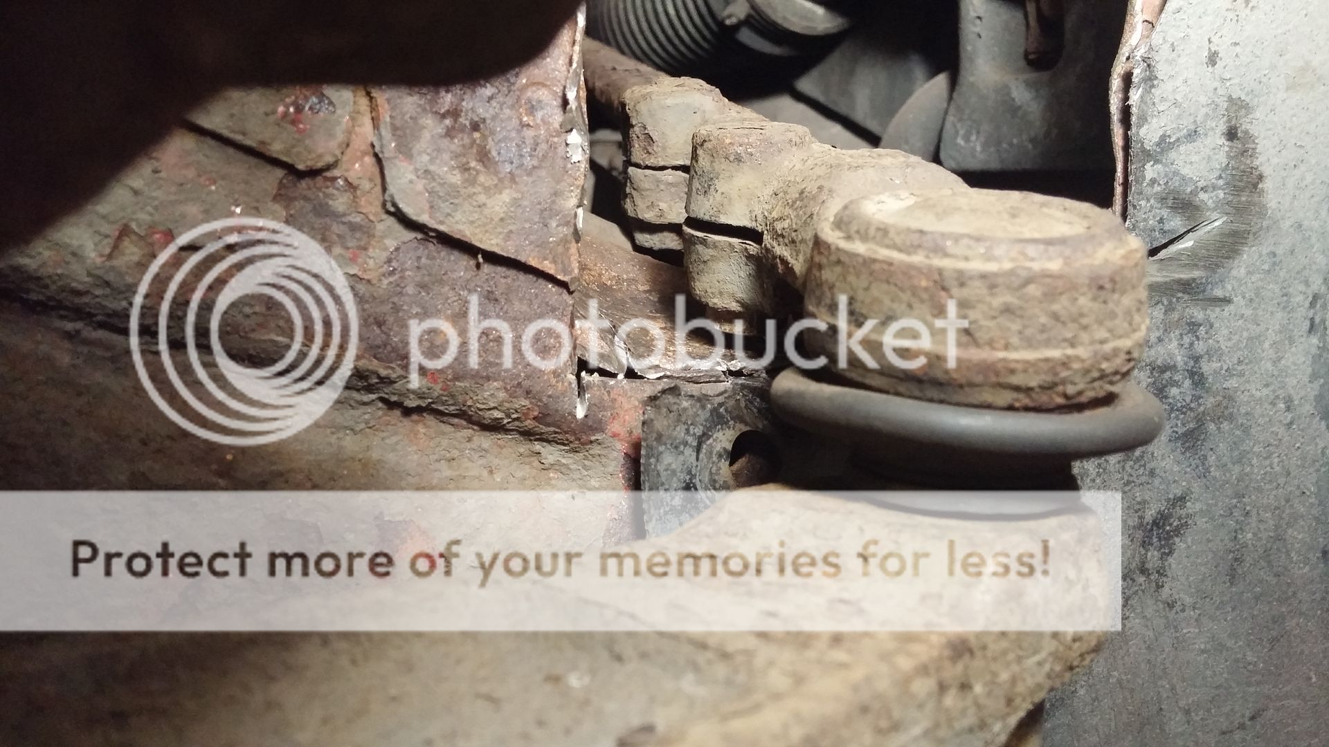
13. Cut out the metal facing you that you marked earlier while trying not to cut too far across the chassis rail. Pay more attention to the forward edge as that is where the bolt on the TRE will catch when on full lock.
14. Take your big hammer and start bashing the chassis rail down to the new level. It needs to be fairly level from your new edge to at least half way across the width of the chassis rail.
15. Once you've bashed the Bejesus out of the chassis rail and are happy it is low enough, then refit the strut and the bottom bolt but not the top one and don't tighten up the TRE. A jack under the brake disk will help getting it in position.
16. Fit the new top camber bolt with the camber pushing the top of the strut in. I had to cut the tab off my camber bolt washer as it fouled the edge of the strut.
17. Push the TRE into it's hole with a gentle tap from a hammer then take the nut from the old bolt and and use it as a spacer on the TRE and screw the TRE nut on finger tight.
18. Turn the wheel to full lock and marvel at how you got the cut out completely wrong. This is why the TRE bolt is in finger tight, remove it and tie the TRE up out of the way while you start bashing the beggar again with a hammer.
19. Repeat 18 multiple times until you have full lock.
20. Repeat on the other side, this time you need to move the coolant header tank out of the way to get the top strut nuts off.
21. I don't know how important it is but I plan to weld the chassis rail before painting.

20160831_215823_zpsquj2je8b.jpg

20160831_215806_zpsn1y24jke.jpg


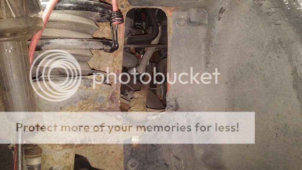
This photo gives you a good idea how far you need to cut down if you look at the position of the missing plastic rivet. I got it completely wrong initially and gave myself a load of extra work.
 
Last edited:
The rears are easier then the fronts but not without their issues. The flexi brake hose goes from the chassis to the strut then a solid connection goes from the strut to the wheel hub. This means that for you to remove the strut you need to disconnect the flexi hose either at the chassis or the strut. Either way you are in for trouble as the solid pipe will probably be welded to the nut so that it twists as you loosen it. I'd advise you disconnect at the strut end because it is a whole lot easier to replace the short pipe than the long one which goes towards the front of the car. I had to replace both on the passenger side as the brake pipe was leaking before I touched it.
So here goes.
Tools required.
Long breaker bar
Hex Socket set
Spanners
Brake pipe crimping tool
11mm brake pipe spanner
Spare parts required
Brake pipe
Brake pipe unions
Or just buy the brake pipes ready made.

1. Remove plastic panels in the boot which cover rear strut turrets.
2. Jack up rear of car and remove wheels
3. Remove the nuts from the two bolts at the bottom of the strut but don't tap them out yet.
4. Release the ABS cable and try to loosen brake pipe union where it joins the flexi pipe at the strut.
5. Realise the pipe is twisting with the union, swear, run and make up a new pipe the correct length and then carry on disconnecting the union and trashing the pipe.
6. Now with a bowl collecting the dripping brake fluid (unless you have a brake pipe crimp but I don't like them as they can damage the pipes or had the sense to cut the pipe which isn't going to survive anyway and fold it over) release the two large bolts.
7. Remove the three turret nuts and the strut should fall out fairly easily.
8. bolt on the 50mm lift kit and refit. A bit of pushing and pulling is required but a jack under the hub will help get it into position.
9. Reconnect the brake pipe and refit ABS cable
10. Bleed your brakes
 
Last edited:
I'll use this post to describe the process for the rear wheels later.
Looking forward to it.
I read elsewhere that the 40mm lift was less troublesome and you really think it would cut down on the cut and shut? The metal on mine is in really superb nick so hacking it seems a shame.
 
Looking forward to it.
I read elsewhere that the 40mm lift was less troublesome and you really think it would cut down on the cut and shut? The metal on mine is in really superb nick so hacking it seems a shame.
Yes, less metal work needed for 40mm ;)
 
All this cutting and shutting is starting to remind me of Project Binky, and the problems they had with the body work and setting up the steering geometry!

 
They have an excellent reputation for doing it right so I can only presume they cut the end off, clean all the disks and make a better job than I ever could of welding it back together. Then through experience and experimenting they know exactly what fluid and how much of it to put back in.
If i had half a brain I would have gone with a Bell unit but I'm to stupid and too tight so end up giving myself a load of extra work.

I'm having Bell fit me a new VCU and bearings next tuesday so I'll report back on how they've done it next week
 
Back
Top