plus not forgetting there’s normally 3 x connectors behind the front passenger side wheel arch liner but as urs is after 2007 they will be behind ur passenger side headlight , these are used by the BCM and TCM along with suspension and EPB
You are using an out of date browser. It may not display this or other websites correctly.
You should upgrade or use an alternative browser.
You should upgrade or use an alternative browser.
Disco 3 (LR3) Steering Angle Readings....Curious!
- Thread starter Saint.V8
- Start date
This site contains affiliate links for which LandyZone may be compensated if you make a purchase.
- Posts
- 16,482
All earths check out perfectly, annoyingly!!!
I will check the other areas you mention when I have calmed down a bit as this is doing my nut in at the moment!
I gave the Yaw Sensor a new earth and also a new positive direct to the battery:
But made feck all difference - I even unplugged the sensor and the Live Data still gave spurious readings....
So I have given it a new power feed, new earth and run two new wires directly to the ABS ECU so it has bypassed ALL connections in the vehicle and it still says something stupid - with BOTh sensors - the chances of both sensors being bandy and/or both ABS ECUs being bandy and giving the exact same error and exact same readings are quite remote.
It is also a replacement Steering Angle Sensor and while I changed it I checked the collar on the shaft and that is all good.
I may see if I can get a replacement TCCM even though there is nothing seemingly wrong with the current one....but these are also a known trouble spot!
Grrrrrrr..........
All earths check out perfectly, annoyingly!!!
I will check the other areas you mention when I have calmed down a bit as this is doing my nut in at the moment!
I gave the Yaw Sensor a new earth and also a new positive direct to the battery:
But made feck all difference - I even unplugged the sensor and the Live Data still gave spurious readings....
So I have given it a new power feed, new earth and run two new wires directly to the ABS ECU so it has bypassed ALL connections in the vehicle and it still says something stupid - with BOTh sensors - the chances of both sensors being bandy and/or both ABS ECUs being bandy and giving the exact same error and exact same readings are quite remote.
It is also a replacement Steering Angle Sensor and while I changed it I checked the collar on the shaft and that is all good.
I may see if I can get a replacement TCCM even though there is nothing seemingly wrong with the current one....but these are also a known trouble spot!
Grrrrrrr..........
oh mate , really feel for u as indeed can see how much attention and care you’ve taken with this
please forgive me if I ask any daft questions , lol
if u drive it down the road do those yaw sensor live data screen figures change at all plse,
was the yaw module new or second hand plse and see it’s the correct one being after 2007, also haven’t heard they req recalibrating but wonder driving the vehicle for a certain amount of time resets them or does it straight away , I’ll dig a bit further into that as well for u just in case ??
as you’ve changed and reset the steering wheel angle sensor I assume that now reads 0 with the wheel dead straight
once again apologises for all the questions , just trying to understand it the best I can , did also take some screen shots and hope u didn’t mind but posted them here just in case any one of us can see something that may assist u
will keep going though all the data and links I have to see if I may be able to find an answer
indeed weird that u have the 5vdc supply at the yaw module along with earths but doesn’t change
all The best to u ant and did u manage to double check those connectors at the back near side wheel along with the 3 x connectors behind ur near side headlight , don’t know if the earth post is still behind the near side front wheel arch liner or has also been moved to behind the headlight with the other 3 x connectors
know the TCM, ECM and I think the EPB also uses those earth post connections , thks
Last edited:
Know this is duplicate of what I posted in the D3 forum
Apologises if you’ve already seen this , I just looked out of curiosity to see what components were linked into the yaw sensor
Wondered if the wheel speed sensors, brake light switch is all ok as part of eliminating them within the list ??, think I read you’ve replacing the brake light switch already
Sorry me waffling , just thinking out loud so to speak
The anti-lock control - traction control system is based on the 4 channel Bosch 8.0 system and provides the following brake functions:
Anti-lock Braking System (ABS).
Corner Brake Control (BC).
Dynamic Stability Control (DSC).
Electronic Brake-force Distribution (EBD).
Electronic Traction Control (ETC).
Emergency Brake Assist (EBA).
Engine Drag-torque Control (EDC).
Hill Descent Control (HDC).
The system consists of the following components:
• A DSC switch.
An HDC switch.
An HDC relay.
A stoplamp switch.
Four wheel speed sensors.
A yaw rate and lateral acceleration sensor.
A steering angle sensor.
• Warning indicators; four on vehicles with a high line instrument cluster and five on vehicles with a low line instrument cluster.
• A Hydraulic Control Unit (HCU) with attached ABS module.
- Posts
- 16,482
Figures don't change at all - stuck at those in the video.
Voltage to sensor is 12vdc from fuse 37, the same fuse that feeds voltage to the ABS ECU on pin 25 I think it is (Light Green).
All other sensors report int othe ABS Module fine, Brake Switch is fine, all speed sensors read perfectly with no spiking when driving.
Have to see if the earth points are behind the lamp or not as you say, but considering the rest of the car works perfectly well, no issue with anything else - only the Yaw Sensor - I could assume the other earth points are sound, but will check them.
Figures don't change at all - stuck at those in the video.
Voltage to sensor is 12vdc from fuse 37, the same fuse that feeds voltage to the ABS ECU on pin 25 I think it is (Light Green).
All other sensors report int othe ABS Module fine, Brake Switch is fine, all speed sensors read perfectly with no spiking when driving.
Have to see if the earth points are behind the lamp or not as you say, but considering the rest of the car works perfectly well, no issue with anything else - only the Yaw Sensor - I could assume the other earth points are sound, but will check them.
many thks , have sent u some other test details
also found this with regards to the connections onto ur ABS module, hopefully its Useful to u
indeed know where ur coming from with regards to the grounds, just been trying to rack my brains in what possibly could be the issue , doesn’t make it easier where the wires go into connectors by the drivers side footwell / passenger side fuse box and main fuse box
sierrafery
Well-Known Member
- Posts
- 18,420
- Location
- Arad/Romania
After all this troubleshooting i'm affraid that it's some ECU fault or even worst an interruption in a link between ECUs... a real nightmare 
After all this troubleshooting i'm affraid that it's some ECU fault or even worst an interruption in a link between ECUs... a real nightmare
plus 1 as indeed a nightmare
know when I had my interior air bag issue it took me ages in having to trace the system one wire at a time , indeed so weird with the yaw module data not changing , shame Ant wasn’t nearer as have the gap iid and an Autel MX808 so could have least plugged mine in to see if they could go deeper within the system
as a side note am wondering about the alarm module that sits behind the head liner where it would set the alarm off if the vehicle is jacked up etc , been trying to see if that ties in with the yaw sensor, ( bottom right of picture )
also wonder why on the canbus testing there’s low Vdc between pins 14 - 4 and 14-5 should have been 2.5 Vdc, so from that I assume that there’s an issue with the chassis ground and signal ground on the low canbus side
6-14 = 59.8 ohms
3-11 = 62.2 ohms
6-4 = 2.4V
6-5= 2.4V
14-4 = 1.33V
14-5 = 1.33V
OBD2 PIN identifications
Pin 1
Pin 2 - PWM positive
Pin 3 - medium canbus ( high side )
Pin 4 - chassis ground
Pin 5 - signal ground
Pin 6 - high canbus (high side )
Pin 7 - K line
Pin 8 - transmission module
Pin 9 - ABS module
Pin 10 - PWM Negative
Pin 11 - medium canbus ( low side )
Pin 12 - restraint control module
Pin 13
Pin 14 - high canbus ( low side )
Pin 15
Pin 16 battery voltage
Last edited:
- Posts
- 16,482
CAN works fine and CAN Low should read 1.3 - 1.5vdc from what I have researched previously. Also, Signal Ground and CHassis ground are the same thing and resistance between both is full continuity. Also CAN High and CAN Low both share the same ground so it is not a CAN Low ground issue as it is a common signal ground between both High and Low CAN and also the Medium Speed CAN.
Also, if I interrupt the CAN the car won't start and the indicators flash etc etc....this makes me sure that the CAN is operating correctly when the ignition is on....
What I want to know is why the CAN shorts to ground when the ignition is off.
Also, On the note of ECU issue causing the fault- I have tried replacement ABS ECU's and Yaw Sensors AND remade the wiring between them and still have the fault which confuses me....
The only other thing i can think of is an iffy TCCM so i may see if I can source a replacement and try it out!
sierrafery
Well-Known Member
- Posts
- 18,420
- Location
- Arad/Romania
Check this out https://support.enovationcontrols.c...494-CAN-BUS-Troubleshooting-Guide-with-Video-CAN works fine and CAN Low should read 1.3 - 1.5vdc from what I have researched previously. Also, Signal Ground and CHassis ground are the same thing and resistance between both is full continuity. Also CAN High and CAN Low both share the same ground so it is not a CAN Low ground issue as it is a common signal ground between both High and Low CAN and also the Medium Speed CAN.
- Posts
- 16,482
Oh, I could be wrong, but from what I had researched previously CAN Low can be read as 1.33 to 1.5V - I will read the article with gusto and recheck!Two things come to mind
1, should the sensor get 12v? As lots run at 5v
2, I think Can voltage should be nearer 2.5v, this is from my work on trucks so cars might be different
As per the wiring diagram:
The Sensor receives 12V from Fuse 37 from what I can deduce.
No worries, always worth checking.Oh, I could be wrong, but from what I had researched previously CAN Low can be read as 1.33 to 1.5V - I will read the article with gusto and recheck!
As per the wiring diagram:
View attachment 287537
The Sensor receives 12V from Fuse 37 from what I can deduce.
- Posts
- 16,482
Further to:
EDIT: DISREGARD THE BELOW - I HAD THE TCCM MODULE DISCONNECTED HENCE THE NO CONNECTION AS THE CAN LOOPS IN AND THEN OUT OF THIS>>>>>>doh!!!!
Just been out to recheck some readings.....
HSCAN H to HSCAN L resistance reading (battery disconnected obviously) is now reading 122Ohms.....ooooooh!!!!
Disconnected ABS Module - no difference
Disconnected Instrument Cluster - goes open circuit
ooooooooh.!!!!!!
Tried the other ABS module - still reading 122Ohms......oooooooh!!!!!!
Measured continuity on the HSCAN L&H from ABS connector back to the Diagnostic socket - both open circuit.....oooooooooh!!!!!!!
My curious question is - how come I can get the Diagnostics to communicate with the ABS Module and get wheel speed readings, brake pressure readings etc etc if there is no CAN connection??????????????????
Last edited:
- Posts
- 16,482
Measured the voltages on HSCAN H and HSCAN L again - still reading a 1.34 - 1.37V ......hmmmmmm
So went round unplugging in turn all the ECU's on the HSCAN on my D3
SAS - No Change
EAS - No Change
Terrain - No Change
SRS - No Change
ECM - No Change
TCCM - No Change
EPB - Voltage jumped to 2.02V - ooooooooh!!!!!!!!
Will report further findings shortly.....
So went round unplugging in turn all the ECU's on the HSCAN on my D3
SAS - No Change
EAS - No Change
Terrain - No Change
SRS - No Change
ECM - No Change
TCCM - No Change
EPB - Voltage jumped to 2.02V - ooooooooh!!!!!!!!
Will report further findings shortly.....
sierrafery
Well-Known Member
- Posts
- 18,420
- Location
- Arad/Romania
I WAS WRITING THIS WHILE YOU POSTED:
Long thread and i dont remember everything which was discussed, i'm clutching at sraws now but at this point if you didnt do it untill now unplug the yaw sensor and read codes that way to see if you get an open circuit or some other than the current codes then do that with the lateral accelerometer too... if you dont get a new code this way and AFAIK you checked all the continuity then IMO it's an ECU problem or in the instrument pack where i think the gateway for the diagnostocs is. I've seen such oddities on my wife's Hyundai when there were "stubborn" codes for the ABS while everything in that area was OK and the problem was with the instrument pack where the diagnostics gateway is on that vehicle. To rule out things following this theory you should unplug other ECUs start with the TCCM module first... or did you try to read codes with TCCM unplugged? would be a good test
then i saw
You might be on the right track now, fingers crossed
i even prepared you the module communications network diagrams for this:
 docdro.id
Long thread and i dont remember everything which was discussed, i'm clutching at sraws now but at this point if you didnt do it untill now unplug the yaw sensor and read codes that way to see if you get an open circuit or some other than the current codes then do that with the lateral accelerometer too... if you dont get a new code this way and AFAIK you checked all the continuity then IMO it's an ECU problem or in the instrument pack where i think the gateway for the diagnostocs is. I've seen such oddities on my wife's Hyundai when there were "stubborn" codes for the ABS while everything in that area was OK and the problem was with the instrument pack where the diagnostics gateway is on that vehicle. To rule out things following this theory you should unplug other ECUs start with the TCCM module first... or did you try to read codes with TCCM unplugged? would be a good test
then i saw
SAS - No Change
EAS - No Change
Terrain - No Change
SRS - No Change
ECM - No Change
TCCM - No Change
EPB - Voltage jumped to 2.02V - ooooooooh!!!!!!!!
You might be on the right track now, fingers crossed
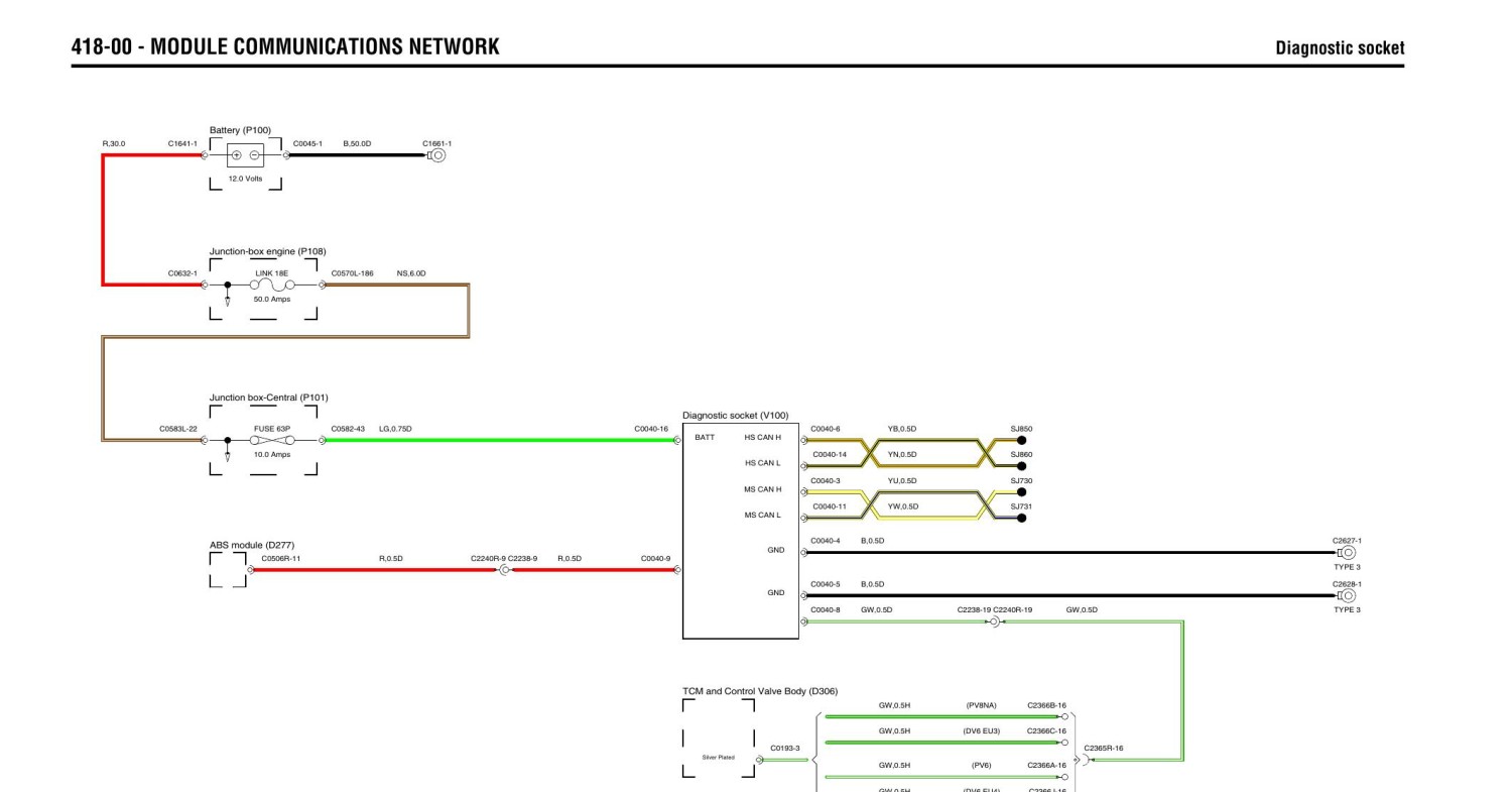
i even prepared you the module communications network diagrams for this:
D3 modules comm network.pdf
418-00 - MODULE COMMUNICATIONS NETWORK. Diagnostic socket 418-00 - MODULE Diagnostic COMMUNICATIONS socket NETWORK. Battery (P100) R,30.0. C1641-1. C0045-1. B,50.0D. C1661-1. 12.0 Volts. Junction-box engine (P108) C0632-1. LINK 18E. C0570L-186. NS,6.0D. 50.0 Amps. Junction box-Central (P101) ...
docdro.id
Got everything crossed for u mate , indeed strange why the abs module is reading 120 ohms instead of 60ohms, alas know one of the 120ohm resisters is in the abs module
hopefully that epb connection at that back rear wheel that goes to the EPB is faulty of the EPB itself
indeed plse keep us informed , really hope ur now able to start pinning the error down, plus good call with regards to unplugging the yaw sensor to see if it changes
plus apologises as assumed it got 5vdc and not 12vdc , had just seen many other modules had the usual 5vdc reference voltage
following with great interest
Last edited:
Two things come to mind
1, should the sensor get 12v? As lots run at 5v
2, I think Can voltage should be nearer 2.5v, this is from my work on trucks so cars might be different
also thinking the same with regards to the 2.5 Vdc , wonder with the reading being 1.34 if there’s a bad ground one one of the modules
ie , am hoping it’s that back left rear wheel connector that goes onto the EPB
great that Ant is able to do this work himself as god know what the bill would have been if had been at a dealers
personally had an issue from the earth connections behind the front wheel arch that the TCM and ECM use , then of course there’s the other earth connections behind the drivers side front wheel arch liner and behind the air box and headlights
curious as it’s a 2007 where they moved the 3 x connections to behind the passenger side headlight if they also moved the earths
indeed time will tell
hi mateI WAS WRITING THIS WHILE YOU POSTED:
Long thread and i dont remember everything which was discussed, i'm clutching at sraws now but at this point if you didnt do it untill now unplug the yaw sensor and read codes that way to see if you get an open circuit or some other than the current codes then do that with the lateral accelerometer too... if you dont get a new code this way and AFAIK you checked all the continuity then IMO it's an ECU problem or in the instrument pack where i think the gateway for the diagnostocs is. I've seen such oddities on my wife's Hyundai when there were "stubborn" codes for the ABS while everything in that area was OK and the problem was with the instrument pack where the diagnostics gateway is on that vehicle. To rule out things following this theory you should unplug other ECUs start with the TCCM module first... or did you try to read codes with TCCM unplugged? would be a good test
then i saw
You might be on the right track now, fingers crossed
i even prepared you the module communications network diagrams for this:D3 modules comm network.pdf
418-00 - MODULE COMMUNICATIONS NETWORK. Diagnostic socket 418-00 - MODULE Diagnostic COMMUNICATIONS socket NETWORK. Battery (P100) R,30.0. C1641-1. C0045-1. B,50.0D. C1661-1. 12.0 Volts. Junction-box engine (P108) C0632-1. LINK 18E. C0570L-186. NS,6.0D. 50.0 Amps. Junction box-Central (P101) ...
As a side note I Must confess I got caught out a few times when testing continuity
Passed using a multimeter and the same with a test light that had a LCD display , However it failed using a test light fitted with a conventional bulb , assume it was because I put the system under load due to the bulb
Cannot beat a load/bulb test on wiring.hi mate
As a side note I Must confess I got caught out a few times when testing continuity
Passed using a multimeter and the same with a test light that had a LCD display , However it failed using a test light fitted with a conventional bulb , assume it was because I put the system under load due to the bulb
Similar threads
- Replies
- 0
- Views
- 760