Series 3 fuel priming issues

This site contains affiliate links for which LandyZone may be compensated if you make a purchase.
IMHO, @Turboman has the right answer.......

Did I mention the filter and case is only £24 ?? :D:D


Delivered:D:D:D

Thats a good picture, which shows how it should be piped up too - the spills go to the top union on the filter... etc. etc. ....
 
the pump is working well on the hand lever, i removed the out union and if really fires out diesel.

the diesel comes out the oump body screw really well, with force, but just not on the control cover, (ref haynes manual photo of which is which. )

So if you got good fuel flow it can't be e filters in the system but what is the fuel flow like when cranking as it's quite easy to install this pump with the lever not on the crank so turn the engine over and see how much fuel flow you have.
Bleed as above.
Don't matter if you loosen top and bottom of the high pressure hoses but you do need to release the air from the top.

Can you see fuel running back down the drip rails?

The one in our s11 was always quite straight forward.

Standard system usually works well if well maintained.

His has been cut about on the LP side, may have created dead ends and air traps that are making it impossible or difficult to bleed.
 
So is the fuel coming through in Good quantity under engine cranking?

System may be chopped about but if the flow is not there when cranking it's problem is fundamental.

If it is connect a clear pipe (via a rubber one) to the pump outlet and crank, you will then see the air being drawn into the system as bubbles in the pipe identifier pipe.

As you can see it you can solve it by checking every joint from tank to pump outlet, got me out the doo a few times for sure.

Go look for old copper washers and Ptfe tape.

I once had a very long discussion with a non convinced boat owner about PTFE tape as he had it on every joint and argued when I took it off, fact boat was now running and would not before did not alter his thoughts.....
It dont let diesel out but it lets air in!
 
wow, thanks for all the input, i was away green leaning in Thetford yesterday, but i'm back on the Land Rover today ,and determined to get it going!!

Ill just go over a few points and try and make it all clear and add a couple more photos.
So.

-That Halfords fuel pump has been in it for the 3 ish years i have owned it and its worked fine, however i take your advice and will get a different one.

- I will take the outbound hose of the fuel pump, double check it with the hand prime lever and then with it running off turn over, to check that it has been fitted with the lever on the cam.

- I think the core of the problem is that in haste i must have plumbed the system incorrectly.

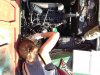
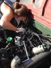
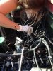
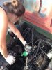
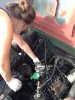
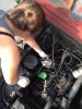
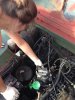
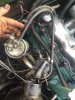
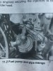
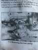
- I have attached some photos of when i fitted the 'new' injector pump about 16 months ago. I can ref these images for the hose set up as it was prior to the engine coming out. Although it is not 100% clear from the photos.

-the cut out lever is in a downward position, held down with a long spring , that i can only attach to a part of the chassis.

----

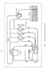
- I will set the pump up today as follows.

- main line from tank in to pump,
-2 lines out of pump,
-one to the outer connector of the fuel filter,
- from the central out of the fuel filter to the in on the top of the injector pump.
-out on the bottom of the injector pump, and spill line from the end of the injectors , return to fuel tank.
- that leaves a out line form the pump,(where does this go?)

Does that sound correct? It sounds more accurate than the way i have it currently!!! I think i just pushed the closes pipe onto the nearest union!!

Ill set it up like that for now, and check back on here for any advice on the second line out from the pump.

This is the CAV manual i was referencing

http://www.bluemoment.com/manuals/Lucas CAV DPA injection pump instruction book.pdf

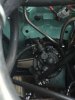
Ill also add additional photos of what i have done today.

Thanks in advance

Jamie

Its my very capable girlfriend before you ask!
 

Attachments

  • IMG_0388.jpg
    IMG_0388.jpg
    325.4 KB · Views: 151
  • IMG_0389.jpg
    IMG_0389.jpg
    312.8 KB · Views: 172
  • IMG_0390.jpg
    IMG_0390.jpg
    318.7 KB · Views: 137
  • IMG_0404.jpg
    IMG_0404.jpg
    310.5 KB · Views: 162
  • IMG_0405.jpg
    IMG_0405.jpg
    311.2 KB · Views: 136
  • IMG_0406.jpg
    IMG_0406.jpg
    310.6 KB · Views: 150
  • IMG_0407.jpg
    IMG_0407.jpg
    322.8 KB · Views: 135
I think the core of the problem is that in haste i must have plumbed the system incorrectly.

I'd agree - and I think that the two outputs from the pump might be your problem - I think the system should be something like:-

Tank - line to inlet on lift pump - lift pump - line to inlet on filter - filter - line out of filter to inlet on FIP - spill from pump back to either the lift pump inlet, * or tank - AND - spill from injector back to tank or lift pump inlet.

* = this is where I think you have mis plumbed it all - the double connector on the lift pump should be on the inlet side.

The standard filter, which I linked to above, achieves this in the simplest way, and I think this is your best way
forward.

Also - please don't take this the wrong way, but try and proof read posts a bit more accurately; viz:-

That Halfords fuel pump <snip>

- you mean the filter, I know you mean the filter, but..... :)
 
Hello again.

So we had some joy yesterday. But still some confusion!
image 7090- shows how the pump was set up at the beginning of the day. with the double banjo on the outlet. This is also how it looks in the Haynes manual, image also attached. (7137, 7138)
I traced the fuel lines back , and defiantly have the out from the tank going to the in on the pump.

I then re plumbed it, into some thing that was more accurate to the CAV manual, (image attached.)

So now it goes,

- OUT of tank, into double banjo on pump
- out of pump to fuel filter
-from fuel filter to IN on top of the FIP
-Back leak pipe on bottom of FIP returns to the double banjo on IN of pump
-Spill pipe on end of fuel injectors returns to tank.

and then...

-The pump was making good pressure by hand, and it was tested open and is defiantly running off the cam.
-There was lots of air coming from Air Vent Screw on Control Cover, then good pressure diesel coming out clear of bubbles.
- However , there was little no nothing happening on the Air Vent Screw on Pump Body.

I then disconnected the Back Leak pipe on the base of the FIP and this allowed more trapped air out. I then tightened everything and turned it over.

Engine started!!

Engine ran about 5 min and then died !!

So it was defiantly diesel line issues. On tick over she sounded great.

I ran it with the pipe from the FIP to the IN of the pump capped, and the out from the FIP just draining out, this cleared air from the base of the FIP, i then quickly re attached this pipe. But i was getting no Diesel out of the Pump Body Vent Screw. At this point the resistance from the hand prime lever just wasn't there any more. I thought potential pump diaphragm damage however, I removed the IN to the FIP and pressured diesel fired out, so it was back pressuring in the pipe and not running through the FIP. After putting it back on there was resistance in the pump, for a few pumps then stopped again, (so no pump issues, but flow issues)

I did a whole bunch more air bleeding and she started a few more times, and ran for about 15 min before stopping again.

Its is obviously better, but im not convinced by the out of the FIP running to the in of the pump, as that is not how it ever was on this vehicle, and nor in the Haynes manual (although to me it makes logical sense )

Any further plumbing ideas, of should i just leave it as is and just , vent again and again and again!!???

Attached is also a close up of the pump configuration. (7132)

the throttle runs wel and the cut out lever works just fine too.

Thanks again


J
 

Attachments

  • IMG_7090.jpg
    IMG_7090.jpg
    314.3 KB · Views: 154
  • IMG_7137.jpg
    IMG_7137.jpg
    405.1 KB · Views: 146
  • IMG_7138.jpg
    IMG_7138.jpg
    392.3 KB · Views: 131
  • Screen Shot 2016-08-30 at 12.18.46.png
    Screen Shot 2016-08-30 at 12.18.46.png
    46.6 KB · Views: 149
  • IMG_7132.jpg
    IMG_7132.jpg
    184.2 KB · Views: 122
You shouldn't need to undo unions all over the place to bleed the system, just the filter head, followed by the pump, followed by HP lines, as I described, should clear the system. Give it another try, in case of residual air. If not, air must be getting in somewhere, as suggested by pete above. Check unions carefully, especially on the line from tank to lift pump.

I don't recall any double banjo on the lift pump on a series? There is none on mine, just a feed to the filter. and that is the same system with a different FIP.
 
The diagram in the landrover manual states excess fuel from injection pump back to double banjo on lift pump outlet.
Spill rail and excess from fuel filter back to tank.page 33 in attached file
 

Attachments

  • SIII_ROM_Part_3[1].pdf
    3.6 MB · Views: 153
OK, well this is how it was set up, with the out from the pump going to the filter (then onto the IN on top of the FIP) and to the Back Leak pipe on the base of the FIP.

So the FIP has inbound pressure on the IN and Back Leak. The Spill pipe is the only one back to the tank, and the OUT from tank is the only one into the pump.

I Think the Back leak on the FIP to the IN on the pump is why it wasn't venting from the Pump Body Vent Screw.

I will re set and test again.

Cheers

j
 
I'm glad you have had it running, using my logic. I suspect, like @Turboman , that you have air getting into the system somewhere - CAV pumps are very intolerant of air IME.

For the system to work as in the manual, there will need to be some one way valves in place, to stop, for example, the FIP getting pressure both on the feed and spill side.

I Think the Back leak on the FIP to the IN on the pump is why it wasn't venting from the Pump Body Vent Screw.

Not sure, but I would be checking for the presence of a one way valve. AND, convert it back to the standard filter set up ASAP - you now know that it runs, so this has got to be the simplest way forward.

@Blackburn - thanks for the manual - here's P33 ....
sys.png
 
Back
Top