Frosted
Active Member
- Posts
- 156
- Location
- North of london
Hi
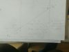
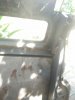
I am rust repairing my Defender and have moved onto the bulkhead. Can you tell me why my bulkhead outriggers are not inline with each other.
It looks like one side has had a new one welded in but I can't tell if it has been put in wrong, it looks like the original outrigger was cut off inline with the outstide vertical face of the Chassis and then the new part of the outrigger welded in.
Who ever did it left loads of weld wire still stuck on!
I had a look at the manual and it seems to say 4 washers between the outrigger and the bulkhead which is correct on the other side, whch I presume is the original (now rusted through outrigger).
But on the newer welded side it is many more washers off.
It that normal ?
I was going to just buy the rusted outrigger but now I am very confused.
Thanks
Last edited:
")