You are using an out of date browser. It may not display this or other websites correctly.
You should upgrade or use an alternative browser.
You should upgrade or use an alternative browser.
Freelander 1 Return of the (Land) Rovers: Kilo-Hippo-Delta
- Thread starter rob_bell
- Start date
This site contains affiliate links for which LandyZone may be compensated if you make a purchase.
Joe_H
Well-Known Member
- Posts
- 1,486
- Location
- Brit in Northern Portugal
Whilst you may well be correct Nodge mate, I would personally not be overly happy - solely from the images and experience.Those cam journals are ok. That's only minor marking, probably from skipped oil changes.
If you are worried, it's easy to measure the bearing play, if you have a dial gauge")
What are the actual align bored bearing surface like ? - that is really important (especially if the cams come from a different head to the one you propose to run them in) - the journal 'in' head bearing surfaces of the original provider of the cams would be a great pointer. - also, how do the scorings on the journals actually 'feel' with the finger test ? - and IF there are ANY in the align bored head bearing surfaces then I would be cautious.
Can you feel a ridge with you finger nail ?
This is one of the issues with align bored alloy with no shells. !
I personally would not be as optimistic as Nodge, (but I fully respect his opinions) However, a picture often fails to tell a thousand words.
Joe
I do indeed. I haven't yet removed the cams from the "good head", but it would be easy to put the in and determine play.
I'd be surprised if there were any to be honest.
What bothers me is how they became scored.
Remember I found that there wasn't and sealant between the carrier and head and the evidence of oil leakage? What if all the damage was secondary to that?
I'm giving myself the fright that the crank journals are similarly fubar'd...
But the engine actually ran as sweet as a nut when I collected it?
Perhaps I'm overplaying this, and I should get on with the head rebuild. And I do have a spare block if needed
Joe, the grooves on the cam are palpable with a finger nail. I haven't bothered checking the scrap head.
I need to check the good head, but am already on the look out for a pair of good MEMS 3 cams. If nothing else, it'd make me feel happier!!!
I need to check the good head, but am already on the look out for a pair of good MEMS 3 cams. If nothing else, it'd make me feel happier!!!
Joe_H
Well-Known Member
- Posts
- 1,486
- Location
- Brit in Northern Portugal
Hi Rob, if they are palpable with the finger nail, then they are totally scrap IMO.Joe, the grooves on the cam are palpable with a finger nail. I haven't bothered checking the scrap head.
I need to check the good head, but am already on the look out for a pair of good MEMS 3 cams. If nothing else, it'd make me feel happier!!!
- they WILL bug8er up a good set of in head journal bearings in another good head.Just far too gone to be serviceable. I feel for ya mate....
Joe
Alibro
Well-Known Member
- Posts
- 7,449
- Location
- Northern Ireland
Turbo would be much better for off roading with the increased torque.
Only sayin like
Only sayin like
You know what, given the way this engine is looking, a complete replacement is becoming increasingly likely!Turbo would be much better for off roading with the increased torque.
Only sayin like
Alibro
Well-Known Member
- Posts
- 7,449
- Location
- Northern Ireland
Yea......
Oops sorry I mean ah poor you.
Seriously though it is a bummer the engine isn't good. Last k series I bought came with suspected hgf but after driving it for a few months there was no sign of it, so I was very lucky. I think the car had been laid up for a couple of years and the guy saw steam from the exhaust and feared the worst.
Having said all that the k series while being perfectly capable on the road and really nice to drive lacks the grunt needed for much off road stuff.
Thanks mate - I am on the look out for a pair of decent replacement cams. Failing that, I may just bite the bullet and lift the whole power train out and think about replacing the engine...!
Sometimes you can strike lucky with K-series cars: some owners instantly fear the worst and have their fears confirmed by garages keen on the money associated with replacing the gasket! (ME? Cynical?) But in this case, I was already thinking that the head gasket had gone, and was prepared for that. I was equally prepared to find that the head was toasted. But the lack of sealant between the oil rail and head, with the resultant scoring of the cam journals was the genuine surprise. Not come across that one before!
But hey, isn't that what these projects all about? It's a journey of discovery really. I can't really have it all easy
Joe, the grooves on the cam are palpable with a finger nail. I haven't bothered checking the scrap head.
I need to check the good head, but am already on the look out for a pair of good MEMS 3 cams. If nothing else, it'd make me feel happier!!!
They don't look to bad on my phone tbh. However I agree that if your nail can feel them, then replacement is a sensible option. I'd still be measuring the bearing clearance though. If the bearings are still inside the service limit spec, there's little to gain by replacing them.
The journal service limit is huge on the K series at 0.150mm.
Cam endfloat service limit is 0.5mm.
So as long us you are under those, you should be ok.
Spent a little while this evening scraping old sealant from the replacement head cam carrier. In general, this head does look so much nicer than the one it's going to replace!
Another look at the cams: I still don't like them, although not quite the nightmare I remember. But the journal bearing surface is not as smooth as the cams taken from the "new" head. Shame these are MEMS 1.9 cams without the reluctor ring!
Another look at the cams: I still don't like them, although not quite the nightmare I remember. But the journal bearing surface is not as smooth as the cams taken from the "new" head. Shame these are MEMS 1.9 cams without the reluctor ring!
Last edited:
Making slow progress at the moment - I've not got a great deal of time during the week to work on cars However, I've taken some more pictures that I thought might be interesting.
First, a comparison between a "good" cylinder head, with proven adequate hardness and a "bad" head, which has turned into a Dairylea cheese triangle.
The key is the width and depth of the indent left by the cylinder liners.
Here is the good cylinder head:
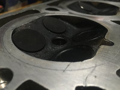
First off, it's clean! But that doesn't necessarily mean that much. But what you can see is that there is a faint ring surrounding the combustion chamber. Run your finger nail over it, and it won't snag in the groove. To finger touch, it will be almost impossible to feel.
Now to the bad cylinder head (from my Freelander):
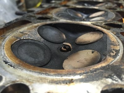
Yes, it's filthy. I'll clean it up and re-take the picture. The head is covered in the residue of failed gasket and coolant/oil (orange in this case) and the black resin from the MLS shim. But look beyond this and the indent ring around the combustion chamber. Particularly to the right bottom corner you can actually see a step in the block face. The ring is broader and much deeper than you'll see on a cylinder head with normal hardness.
If you are faced with this appearance on removing a cylinder head, then I am afraid it's bad news. It's only good for use as a paper weight. Like mine.
However, I've taken some more pictures that I thought might be interesting.First, a comparison between a "good" cylinder head, with proven adequate hardness and a "bad" head, which has turned into a Dairylea cheese triangle.
The key is the width and depth of the indent left by the cylinder liners.
Here is the good cylinder head:
First off, it's clean! But that doesn't necessarily mean that much. But what you can see is that there is a faint ring surrounding the combustion chamber. Run your finger nail over it, and it won't snag in the groove. To finger touch, it will be almost impossible to feel.
Now to the bad cylinder head (from my Freelander):
Yes, it's filthy. I'll clean it up and re-take the picture. The head is covered in the residue of failed gasket and coolant/oil (orange in this case) and the black resin from the MLS shim. But look beyond this and the indent ring around the combustion chamber. Particularly to the right bottom corner you can actually see a step in the block face. The ring is broader and much deeper than you'll see on a cylinder head with normal hardness.
If you are faced with this appearance on removing a cylinder head, then I am afraid it's bad news. It's only good for use as a paper weight. Like mine.
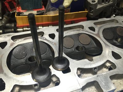
The replacement head is not without problems - at least two of the inlet valves are bent. With the cams removed, the valves should all be shut. But lo: there is light at the end of this tunnel:

There shouldn't be!!! The other ports (inlet and exhaust) are reassuringly dark - here's one example:

Luckily, Dave gave me some spares - although to be honest, with two scrap heads in the garage, I am not really short of replacement valves right now!!!

There shouldn't be!!! The other ports (inlet and exhaust) are reassuringly dark - here's one example:
Luckily, Dave gave me some spares - although to be honest, with two scrap heads in the garage, I am not really short of replacement valves right now!!!
I've spoken to Dave Andrews again - a brilliant guy and amazingly helpful!
Firstly, he can get a head skimmed for about half the price I can locally to me. Okay, I have a 100 mile round trip, but probably worth it because he also can get me a pair of replacement cams!

Unfortunately, this will inevitably slow progress by about a week - but not a complete disaster by any means.
Dave also advised a good test to check on the valves and whether they were bent or not. It would seem that there is sufficient play in the valve guides to allow a slightly bent valve to adequately seat and seal - so a leak-down test would necessarily give the other valves the all clear. In fact it could provide me with a false sense of security - and then, with the repeated hammering the valves get, the valve head could fatigue and fracture and cause spectacular damage.
In fact, I have seen a car where precisely this had happened: the owner (a Japanese re-import MGF VVC) had replaced the cam belt after the original had snapped. He had thought that he'd gotten away with it, but then one of the valves disintegrated in spectacular style, sharing metal swarf with adjacent cylinders.
Any road: back on track! What Dave suggests is to put each valve in the lathe and look for run out. Unfortunately I don't have a lathe, but figure that a pillar drill should be a suitable alternative.
So it would seem that a week's delay will give me time to remove all the valves, inspect and replace!
All good fun of course.
Firstly, he can get a head skimmed for about half the price I can locally to me. Okay, I have a 100 mile round trip, but probably worth it because he also can get me a pair of replacement cams!
Unfortunately, this will inevitably slow progress by about a week - but not a complete disaster by any means.
Dave also advised a good test to check on the valves and whether they were bent or not. It would seem that there is sufficient play in the valve guides to allow a slightly bent valve to adequately seat and seal - so a leak-down test would necessarily give the other valves the all clear. In fact it could provide me with a false sense of security - and then, with the repeated hammering the valves get, the valve head could fatigue and fracture and cause spectacular damage.
In fact, I have seen a car where precisely this had happened: the owner (a Japanese re-import MGF VVC) had replaced the cam belt after the original had snapped. He had thought that he'd gotten away with it, but then one of the valves disintegrated in spectacular style, sharing metal swarf with adjacent cylinders.
Any road: back on track! What Dave suggests is to put each valve in the lathe and look for run out. Unfortunately I don't have a lathe, but figure that a pillar drill should be a suitable alternative.
So it would seem that a week's delay will give me time to remove all the valves, inspect and replace!
All good fun of course.
Joe_H
Well-Known Member
- Posts
- 1,486
- Location
- Brit in Northern Portugal
Hi rob, if you have a guide that fells a good fit on a valve - put the valve in the opposite way around - ie rod end down from the top of the guide - so the valve is sticking up away from the combustion chamber (hope that makes sense ) .. then with the head on its side - the valve into the guide about 20mm, put a straight edge - or anything located well - to just touch the tip of the valve guide and rotate gently by hand from the bottom end near the guide. You should be able to see any run out. Not as good as a lathe but pretty close.
Also, you could try rolling the stem on a truly flat surface - a good replacement for an engineers flat table is a piece of plate glass from your local supplier. Get them to round the edges to stop cuts. You only need about a square foot, thicker the better - if you lightly glue it to a bit of ply off-cut you have a poor mans engineers 'flat'
To really show my age - we used to use the protection glass from the front of the early tv's - 70's ish - loads still about in the 80's. It was the flat glass in front of the CRT as people were not convinced the CRT was not going to implode lol - seriously !.the glass was about 8 or 9 mm thick and optically clear - and solid plate. Everyone I knew had one glued on to a bit of ply - made a fantastic flat plate. Only trouble was the magnetic turn blocks didn't hold
Eeeee, we were poor in them days -.... had to walk to work 20 miles through t'snow.....
Joe
) .. then with the head on its side - the valve into the guide about 20mm, put a straight edge - or anything located well - to just touch the tip of the valve guide and rotate gently by hand from the bottom end near the guide. You should be able to see any run out. Not as good as a lathe but pretty close.Also, you could try rolling the stem on a truly flat surface - a good replacement for an engineers flat table is a piece of plate glass from your local supplier. Get them to round the edges to stop cuts. You only need about a square foot, thicker the better - if you lightly glue it to a bit of ply off-cut you have a poor mans engineers 'flat'
To really show my age
- we used to use the protection glass from the front of the early tv's - 70's ish - loads still about in the 80's. It was the flat glass in front of the CRT as people were not convinced the CRT was not going to implode lol - seriously !.the glass was about 8 or 9 mm thick and optically clear - and solid plate. Everyone I knew had one glued on to a bit of ply - made a fantastic flat plate. Only trouble was the magnetic turn blocks didn't hold Eeeee, we were poor in them days -
.... had to walk to work 20 miles through t'snow.....Joe
Thanks Joe! Well, we do have a glass-topped table in the kitchen... good enough?
What I was thinking of was to run it in the pillar drill down onto an abrasive pad. Then there would be a tell-tale of any run out. Or I could set up a dial gauge.
But perhaps the rolling on a glass top would be the easiest thing to try first!
What I was thinking of was to run it in the pillar drill down onto an abrasive pad. Then there would be a tell-tale of any run out. Or I could set up a dial gauge.
But perhaps the rolling on a glass top would be the easiest thing to try first!
Joe_H
Well-Known Member
- Posts
- 1,486
- Location
- Brit in Northern Portugal
Table should be ok me thinks - but worth getting a foot square plate glass for future use...Thanks Joe! Well, we do have a glass-topped table in the kitchen... good enough?
What I was thinking of was to run it in the pillar drill down onto an abrasive pad. Then there would be a tell-tale of any run out. Or I could set up a dial gauge.
But perhaps the rolling on a glass top would be the easiest thing to try first!
Always tested OHV pushrods that way
Put a straight edge across the glass at various angles, should be perfectly flat, no reason for it not to be - just try not to drop the head on it - the bride might get a 'bit cross'
Joe
Rich in Vancouver
Well-Known Member
- Posts
- 395
- Location
- Near Vancouver Canada
I think you will find the drill has too much run-out.....Unless you are fortunate enough to have a very high quality drill!
Joe_H
Well-Known Member
- Posts
- 1,486
- Location
- Brit in Northern Portugal
Hi Rich, I don't think I have EVER seen a drill with no run out - even some of the top quality press units.I think you will find the drill has too much run-out.....Unless you are fortunate enough to have a very high quality drill!
- a hand held unit would usually make a good substitute for a food mixer........................... Similar threads
- Replies
- 6
- Views
- 366