Removing 3.9 from Discovery

This site contains affiliate links for which LandyZone may be compensated if you make a purchase.
F528CC50-19D5-4F80-A88B-D71A6A4399D6.jpeg
DE1E8610-C743-408E-A6DC-8E8DFA820758.jpeg


what is this gizmo and do I need it? It’s got wires from the engine harness to it and vacuum pipes. One comes from the head. If it’s not doing anything useful I will remove and blank the vacuum pipe
 
View attachment 257176 View attachment 257177


what is this gizmo and do I need it? It’s got wires from the engine harness to it and vacuum pipes. One comes from the head. If it’s not doing anything useful I will remove and blank the vacuum pipe

@Def90man , how did you get on with this...is the engine in yet/wiring plan sorted? Purely being inquisitive would love to know what the minimum wire pinouts are required for a perfectly running 3.9/4.0 with 14cux hotwire.
 
@Def90man , how did you get on with this...is the engine in yet/wiring plan sorted? Purely being inquisitive would love to know what the minimum wire pinouts are required for a perfectly running 3.9/4.0 with 14cux hotwire.


The engine is in and I’ve connected the starter, alternator, throttle cable. Still to find and connect the oil/coolant sensors. Then I’ve got the fuel lines to finish and put pump in tank. Then move to gearbox wiring. Then I hope to look at the efi. From everything I’ve read, a permanent live, switched live, power to pump and an earth is supposed to do it. I’ll need to study the start inhibitor from gear selector to see where to put that in, then gearbox oil cooler.......

I’m hoping to have her running by the end of February but who knows o_O
 
My efi motor is from a 3.9 discovery => fitted into my defender 90.

I've since gone full megasquirt, but certainly making it run on the old efi hotwire rig was no problem at all - trivial enough that I can't actually remember doing it. I will have taken the engine loom, unwound the tape and stripped out all the unnecesessary wiring though. It's not hard, the wiring on these early efi systems is easy.
 
I’ve been looking at the efi wiring and I think I know what’s what. Every search I’ve done about wiring the efi describes a white plug with different colour wires to mine.
I have a brown plug and a white plug by the ecu but I’m sure the brown plug is the one to work with.

On the brown plug I have

a thick brown/green which I think is perm live
a thinner brown/ red - not sure at the moment
White/purple and purple/white which is ign live and feed to fuel pump
White/green - possibly to do with diagnostics

on the white plug I think I have speed transducer
 
Tried wiring up the ecu hoping to here a click or two off the two relays but nothing. I’ve read every write up on the web about how to wire it up but all have different colour wires at the plug. Everyone I’ve read says to put thick brown to permanent live with ignition live to white/slate and white/purple for fuel pump

EBC4E5BB-BBC6-44AE-9BFA-2D63620C0E56.jpeg


I’ve got thick brown/green and thick brown/red, purple/white which should be power to fuel pump relay and a white purple which I’ve put to fuel pump. Also got a thin white/green.
Next to this plug i have a white one which does have a thin white/slate plus I think the transducer wire and possibly the start inhibitor.

29D1A8B6-78F3-4AF2-8E87-E7A4F88378C7.jpeg


I’m kind of stuck now as I don’t want to cook anything :eek:
 
Really recommend you read these before firing up to get to grips with how the 14CUX system really works

https://www.legionlandrover.com/man...oot rover 14cux electronic fuel injection.pdf

And Mark's excellent tech data of his G33 project + 14CUX manuals in dropbox

http://www.g33.co.uk/pages/technical-fuel-injection.html

https://www.dropbox.com/sh/i0acxr8n...a/RoverGauge CD?dl=0&subfolder_nav_tracking=1

Once system understood, then start wiring and finally system test. Importantly is the ignition timing, fuel flow rates, distributor amplifier, understanding the closed-open loop stages, TPS position and importance of the road speed sensor. Good luck...
 
Really recommend you read these before firing up to get to grips with how the 14CUX system really works

https://www.legionlandrover.com/manuales/service and troubleshoot rover 14cux electronic fuel injection.pdf

And Mark's excellent tech data of his G33 project + 14CUX manuals in dropbox

http://www.g33.co.uk/pages/technical-fuel-injection.html

https://www.dropbox.com/sh/i0acxr8nwr10ow6/AADQPWdMniHoZY7DQiPvbLJMa/RoverGauge CD?dl=0&subfolder_nav_tracking=1

Once system understood, then start wiring and finally system test. Importantly is the ignition timing, fuel flow rates, distributor amplifier, understanding the closed-open loop stages, TPS position and importance of the road speed sensor. Good luck...


I’ll have a read tonight. It’s just annoying that the wire colours on mine don’t seem to match all the other conversions that have been done :(
 
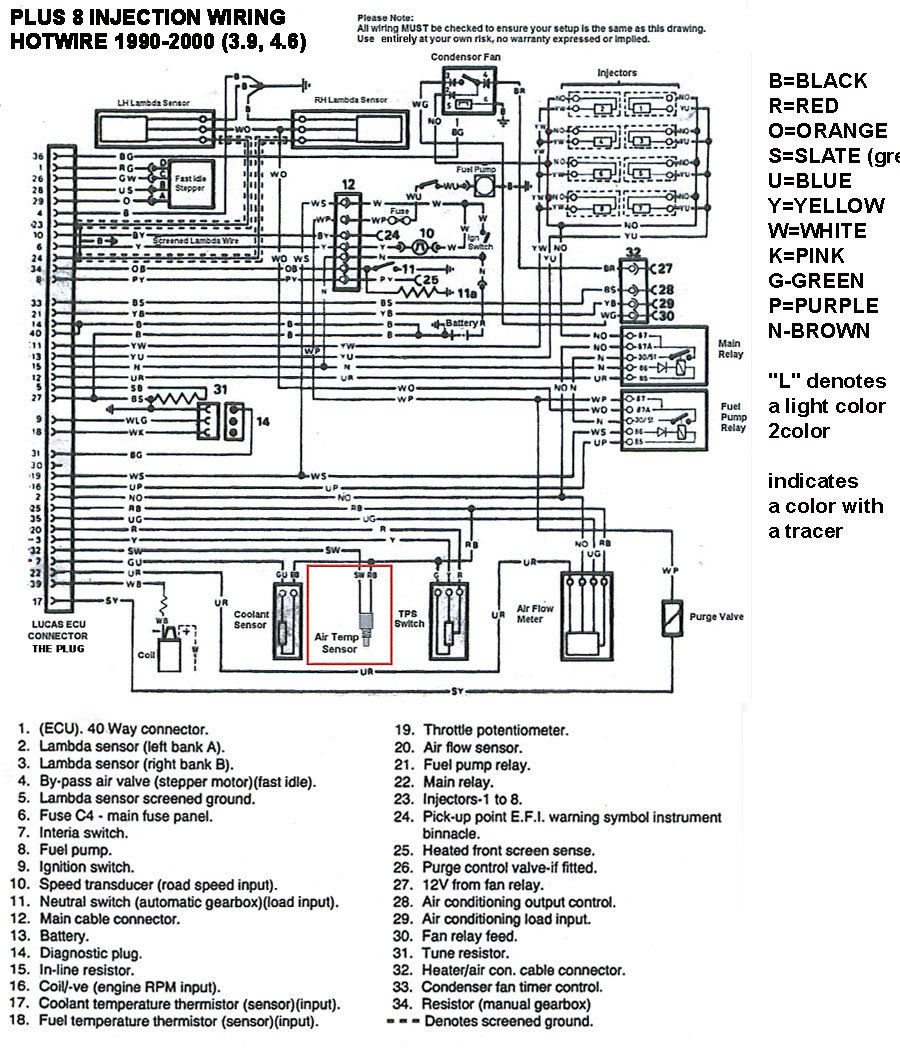
What engine model year and what diag' have you been using? I'd lay out the loom before installing and x-ref' the 14CUX wiring diag', then mark up all primary wires...especially those relayed/supplying 12v to all primary function components...including the injectors, TPS etc. You could/should even bench test with good 12v supply before installation. Then install for test run, then trim wires back for final installation.

Here's std 14CUX wiring diag'

post-4255-125788560871.jpg

it’s a January’95 M reg disco 1 3.9. The whole engine/gearbox loom came out in one so I wasn’t disturbing anything. Everything I’ve read says connect an ecu live, an ignition live and power to fuel pump wire and relays should click. I’ll have another look tomorrow
 
I'd start with clear logical fault finding/cct testing. Start with primary power ccts, then the individual component o/p's, then injector wiring etc. Follow this up using the fault finding notes in links above.

As with all wiring it's going to be a really simple fault, just trace back methodically...and make Go/No-Go notes [test sheet results] as you complete each test. This helps to stop frazzled brain mode o_O
 
Good news ! Brown/green is ecu permanent live, white/green is ignition live and an ignition live to the purple/white and relays are clicking and fuel pump runs for a couple of seconds. Engine coughed quite a few times but wouldn’t quite fire but I’ll do some investigations tomorrow :)
 
Back
Top