Disco 1 How to connect puddle lights?

This site contains affiliate links for which LandyZone may be compensated if you make a purchase.

PierroDisco

New Member
Hello,
I’m the proud owner of a sherished Discovery Tdi (may 1998).
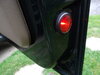
I’ve bought the puddle lights (PRC 8076) for both front doors (with white lens for in the bottom, with red lens for in the valence). They all fit in the holes where now blanked by black buns. Each light has two feeds and is a pushfit with 5 W. They all came from a Range Rover Classic (production ended in 1996).
‘Some’ manuals and my owner guide do mention thes puddle lights but their infirmation is very mimimal. So I think they problably only came with some high end luxureous versions.

How can I connect the two feeding wires of each puddle light ?

Thanks for showing me the light, eh the way !
Pierrodisco
 
Fitted mine years ago on my Discovery 200tdi 1990, no problem that I remember just run a bit of two core cable along the bottom of the door ( obviously inside) keeping clear of the window slides then connect to the interior light circuit, I used a inline 5 amp fuse on the feed,
 
Like I fitted fitted then way back in 1999, I was surprised that they were not fitted, as my RR had, not even to an ES and they weren’t even an option although they are shown in the disco 1 parts catalogue.

I also purchased the door looms to use from the door to behind the footwell kick panels but then had to make my own connections, I just tapped into a permanent live at the fuse box and ground via the interior light door pin, I had to use a diode at each pin to stop interfering with the MFU switching function for the interior lights and alarm. Later I fitted white LEDs to the four lamps for a much brighter light.
 

Attachments

  • 4003B6A9-2A98-46D1-B0DA-05A16E2FE0CE.jpeg
    4003B6A9-2A98-46D1-B0DA-05A16E2FE0CE.jpeg
    198.2 KB · Views: 102
  • 136069D7-F5C2-4411-846D-096ACB3D898F.jpeg
    136069D7-F5C2-4411-846D-096ACB3D898F.jpeg
    391.2 KB · Views: 87
Like I fitted fitted then way back in 1999, I was surprised that they were not fitted, as my RR had, not even to an ES and they weren’t even an option although they are shown in the disco 1 parts catalogue.

I also purchased the door looms to use from the door to behind the footwell kick panels but then had to make my own connections, I just tapped into a permanent live at the fuse box and ground via the interior light door pin, I had to use a diode at each pin to stop interfering with the MFU switching function for the interior lights and alarm. Later I fitted white LEDs to the four lamps for a much brighter light.
 
Hello Discool,

Thanks for the helpfull answer ! I’ve found the wiring harness PRC4802 on the www.
But... my english is not so very good, and mij knowledge of electricity is a quoted a little bit higher than basic !
So, could you please drew a very basic wiring diagram and post it to me (and sorry but I don’t understand the term “permanent live at the fuse box). Anywhere it will help me.
And how can I upload pictures by my posts ? I didn’ t succeed.
Wiring door switches.jpg
20200507_180447.jpg
20200507_180447.jpg
20200507_175815.jpg

Much greetings,
Pierrodisco
 
Hi Pierrodisco

Ok first located fuse 6 at the ‘upper auxiliary fuse panel’ that’s one the six way fuse strips at the side of the main board, fuse 6 is 20amp and yellow.

Fuse 6 is supplied from the engine bay fuse box via a thickish brown/purple wire. So on the incoming side of fuse 6 I crimped a single wire with it own 5amp inline fuse to supply the 12v to both front doors and feed the puddle lamps... obviously that single wire will need to have a (T) joint to enable the 12v feed in two directions.

I used a crimp as that was was available but u may prefer now to use a piggy-back style fuse adaptor at fuse 6, which I didn’t have back in 1999... no internet or eBay.:(

The ground (Earth) from the lamps in each door is a single wire to each door pin terminated via diode to stop interfering with the operation of the MFU... it’s a long while a go ...maybe the interior lights stayed on.
Unless u wish to fit additional door pins just door the puddle lamps.

That’s about it, I didn’t even remove the door cards, just used the various holes at each end to retrieve the wiring loom... slow but doable.
https://www.ebay.co.uk/itm/180735526749
https://www.ebay.co.uk/itm/291036745093
 
Last edited:
Hello Discool,

I’m a little late with replying ; anyway your explanation will do now. Lifetime learning !

But I think that the diode in the single wire between door switch and multifunction unit simply will cut off forever his function for the courtesy lights on the ceiling. The current may not run to the MFU but to the earth from the door switch. Or do I have it wrong ?
And with simply installing a second door switch for each front door, both white and red light just stay switched on as long as the “own” door is opened (without the delay time from both ceiling courtesy lights).

So you have commends on my remarks, they are still very welcome and will be heard...and followed up.

Much greatings from
Pierrodisco
 
Hi Pierro welcome back.
The diode is fitted to the puddle light earth wire just before it terminates at the door pin with the existing wire, not the existing door pin wire that stays untouched
There is no delay in the illumination (door open light On door - closed light Off) what ever way you do the install, existing Door pin or a new additional pin.
 
Back
Top