Fuel and ignition but still won't start...

This site contains affiliate links for which LandyZone may be compensated if you make a purchase.

Jagman

New Member
Posts
46
Hiya, advice needed before I light blue touch paper and stand clear!!

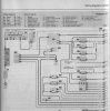
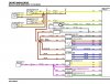
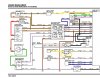
I have a W reg 1.8 petrol hippo that just refuses to start. Nice strong clean spark at the plugs and fuel is reaching the injector fuel rail but when it spins over it just doesn't want to catch. I'm thinking that the fuel is not getting through the injectors and that there is a leccy fault. I see from the Haynes manual that the injectors are triggered from the ECU on one side and are connected to a relay on the other. The relay also has the oxygen sensor going to it but the wiring diagram doesn't show the internal connections of the relay so I'm not able to meter it out. I have a couple of questions, i.e. any ideas where this relay is located? Following the cabling from the O2 sensor doesn't locate it. In addition, I notice on the wiring diagram that injectors for cylinders 1 & 4 are wired in parallel as are injectors 2 & 3. This would mean that when Injec 1 is open on the compression stroke to let fuel in, this would also be the case on Injec 4 which would at that time be on the exhaust stroke. Any ideas how this works please??

Overall, any ideas where to look for a fix to this non starting lump of sh*te??

Ta and Happy New Year to whoever comes up with the correct answer!!

:)
 
Going by your description, (I'll need to check though) The relay is the engine management relay and powers the ecu and other electrical stuff for the engine management. The injectors all have a live feed to them and the ecu switches the earth, no two injectors will be open at the same time. the same relay also powers up the oxygen sensor and the ecu measures the voltage going back.

A relay is wired as follows...... terminal 30 is permenant live, 85 and 86 can be wired either way but one would be an earth (either switched or permenant) and the other would be a live (either switched or permenant), these are for the no load side. Terminal 87 is the load side output.

So it basicallly works like this...... power goes to term. 30, a circuit is created between 86 & 87 by a switch (in this case the ignition switch), this closes the contacts inside the relay to allow current to flow from terminal 30 to 87, out of 87 to the component.

To test for an injector pulse, unplug one of the injectors and connect an LED test light across the pins, crank the engine and the LED should flash.

Other stuff to check.........
Check the compressions
makes sure the plugs arn't soaking wet with petrol
check the fuel pressure, you'll need at least 30 psi to start it, i think it should be about 50 psi
try a known good crank sensor, I've had these pack up in the past
Check the coil, you may have a nice fat spark at ambient pressure but is it sparking under load? i.e inside the cylinder.
 
Hi Clutchdust, thanks for your reply.

Unfortunately the relay in question is shown in the Haynes manual as just one relay with no terminal number but I have since managed to get hold of a copy of the RAVE CD and this shows the modules as 4 standard relays so I can now understand the switching. However, checking the injector wiring, they are definitely wired in parallel in 2 pairs and this can also be seen in the Rave diagrams attached below. The injector connector attached to the fuel rail has only 3 wires so this would also suggest that the injectors are wired in pairs with a common feed/return. The only way that I can see how this could work is if each injector in a pair had a diode wired the opposite way round to its mate and the trigger was sent positive to one injector and negative to the other? A very strange setup, I'd be interested in others comments on this wiring and how it works.

The crank sensor must be ok as this is sending the pulse for the ignition to fire. Good point though about the ignition when under load.
 

Attachments

  • injectors (Haynes manual).jpg
    injectors (Haynes manual).jpg
    132.7 KB · Views: 298
  • Injectors1 RAVE CD.jpg
    Injectors1 RAVE CD.jpg
    103 KB · Views: 327
  • Injectors2 showing relay RAVE CD.jpg
    Injectors2 showing relay RAVE CD.jpg
    130.3 KB · Views: 713
jagman, do you know the arrangment of the inlet manifold/ s, is it common to each cylinder ?
looking at the diagram it would seem that injectors are fired in pairs 1&4 and 2&3
i have seen single point and multi point injection systems, but not this arrangment

i havent had many dealings with petrol injection systems, but i see the arrangment a bit like having twin carbs, as opposed to a single or even 1 carb per cylinder

your arrangment would imply each injector is supplying 50% of the fuel required ,
 
Dude, I have skimmed the text above and you have same symptoms I had 2 weeks ago, was down to leaky injector (No.2 i think it was). Had them refurb'd and refitted and runs like a dream again. Could be any number of other things as well but my mechanic was confident after talking to one of his land rover mates that this ws it, found a little test you can do and lo, i'm a bit poorer but the wife's car starts now

p.s. if i'm way off the mark or have missed anything obvious then soz!
 
However, checking the injector wiring, they are definitely wired in parallel in 2 pairs and this can also be seen in the Rave diagrams attached below. The injector connector attached to the fuel rail has only 3 wires so this would also suggest that the injectors are wired in pairs with a common feed/return. .
yer correct jagman. . . .look at the way the pistons are configured and then youll understand the injector firing order. . . .:)
 
yer correct jagman. . . .look at the way the pistons are configured and then youll understand the injector firing order. . . .:)

Yep, it's the standard 1 3 4 2 configuration. i.e. when 1 is on compression stroke, 4 is on exhaust (same goes for 2 & 3). So, when 1 is on compression, that is when the injector for 1 should open and fuel be injected. With the wiring as it is, this would also inject fuel into cylinder 4 that is on it's exhaust stroke. Not something that you'd want!

Unless you know differently?....... :confused:
 
hey,,hold on a tick ,, correct me if im wrong on this one , but we are talking a petrol 1.8 so injectors should be firing on the induction stroke ???
injectors are fitted in the inlet manifold
 
hey,,hold on a tick ,, correct me if im wrong on this one , but we are talking a petrol 1.8 so injectors should be firing on the induction stroke ???
injectors are fitted in the inlet manifold

OOPS! Yep, me being a stupid bar steward there... of course it opens the injector on the induction stroke, however that would mean that when 1 is on induction, 4 is on the downward power stroke. Are you saying that the injectors are mounted such that they are not one for each cylinder but basically the fuel is just injected into a common manifold so that which ever cylinder is on the induction stroke sucks in the fuel from both active injectors? If so, I can see how it'd work but is that the best way to design a fuel system??

Ho hum, we live and learn! :D
IN A NUT SHELL YES. . . .ahem injectors give high pressure fuel from a high speed solenoid but you still need air so it can go bang wiff a spark plug [not needed wiff a doozle] so it your case inj[1] un inj[4] gets a dose at same time piston 1 is on [fire line] inlet has opened ,ing on fire ex valve opens [git rid er ****e] number four is next [fuel is already there] bang same thing. . . .git it:) :) :)
 
Does seem strange that they are wired like that but lookin at it, I can see that the injectors have a power feed on the brown wire and they are switched by the 2 yellow wires which are earths, why they are wired in parallel is beyond me but there must have been a reason why they did it this way. I wouldn't worry about why its like this, just make sure it works.

With reference to another post about the injectors firing on the exhaust stroke, yeah I see what you mean but it wont matter as the inlet valve will be closed anyway.

The injectors only squirt when the inlet valve is closed, they don't squirt throughout the duration of the intake stroke like most people think.

A measured amount of fuel is injected before the valve opens, then the cylinder draws the mixture in when the piston goes down and the valve opens.

All makes sense now.... Until I had a proper look, I thought the injectors were direct into the cylinders the same as a deisel injector is (or even a spark plug) so that's why I couldn't understand why fuel would be injected into a cylinder when it was on the power or exhaust stroke. I know now that they inject in pairs into the common intake manifold so it makes sense (even though I still think it's a crap design!).

Thanks to everyone for their replies and may yer Hippos not skint yer during 2008! :D
 
Back
Top