Diesel Do
Well-Known Member
- Posts
- 5,215
- Location
- Nottingham
Nice to hear. That's what most people find. I can't get my head around the negative comments that have been chucked at Alibro.
Lets just say it's my fault! That's what my wife always says anyway.Nice to hear. That's what most people find. I can't get my head around the negative comments that have been chucked at Alibro.

The lift will probably shorten the life of the drive shafts (CVs) though. That's not a negative comment - just a price you pay for having the ground clearance.
Ahh, I never thought of that.I extended the wheel end rather than cutting the tube. Lengthened and braced the u shape bit that goes around the bush
Doing that will be strong enough. If you cross drill the outer tube you can puddle weld through the holes too.
Lets just say it's my fault! That's what my wife always says anyway.
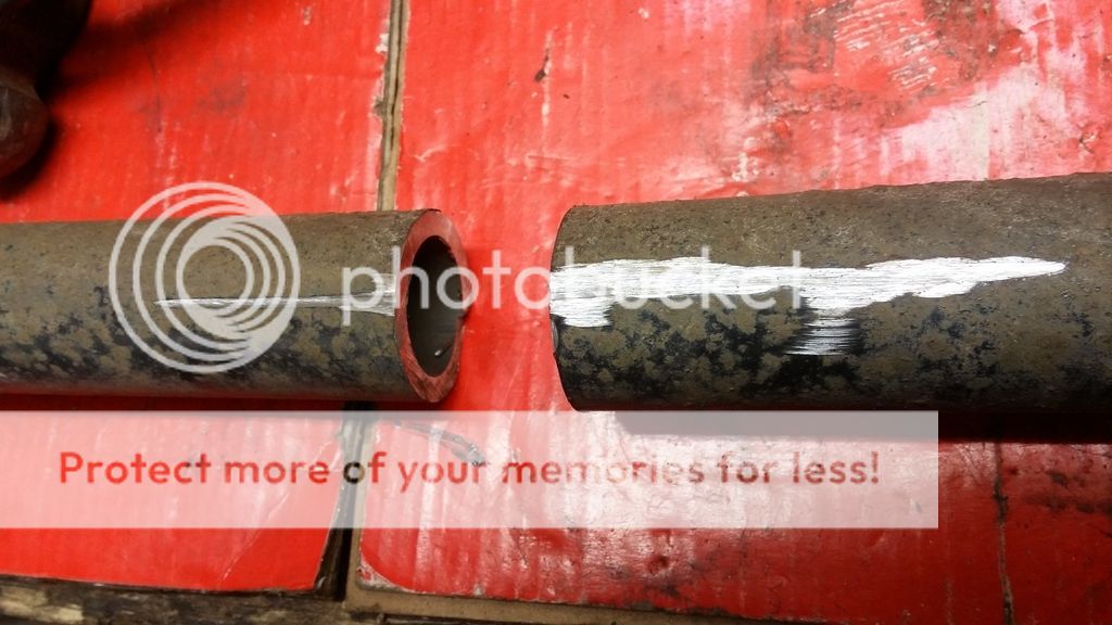
The new arms arrived today so tonight I stuck them in and then had a wee look at the old ones.
This is what they look like when cut in half.
I measured the gaps between the wheel arches and found I need to move the wheel forward by 17mm to bring it into the middle. As the gap to the front was 45mm on full compression (nearly) I'm happy there is will be plenty of margin if I move the wheel forward by this much.
I'd thought of that too Nodge but for now I'm going to go ahead with 17mm as that will bring the wheel back to centre. If I find it catches when off roading I can always do another set which are adjustable but I don't think it will be a problem.You could probably weld in the adjuster section from the rear suspension lower arm. This would allow the adjustment to be set at what ever gives the perfect geometry
No idea but when off roading they will all take a battering so need to be over engineered.I have no idea as to the answer of this, but are the suspension arms designed to take as much force as the trailing arms?
The trailing arms will take smaller loadings than the lower armsI have no idea as to the answer of this, but are the suspension arms designed to take as much force as the trailing arms?
.'Pends on how steep the hills I'm climbing are.The trailing arms will take smaller loadings than the lower arms
The tie bar is under compression while moving forward. It'll be fine with a 3mm tube slid over the current bar. Drill some large holes in a four places on each end so you can plug weld the inner to the outer. Then seam weld the ends. Weld it like that and it won't be braking in use.'Pends on how steep the hills I'm climbing are.
I was concerned 3mm may not be enough as the original is 4mm although smaller diameter. I'll try to find something to go inside as well. Like I said before I've been there and seen my efforts fail quite spectacularly so don't intend it to happen again. I'll take a look for the photos and post them for your entertainment.The tie bar is under compression while moving forward. It'll be fine with a 3mm tube slid over the current bar. Drill some large holes in a four places on each end so you can plug weld the inner to the outer. Then seam weld the ends. Weld it like that and it won't be braking in use.
I quite fancy a wind turbine myself. Although I could get away with a small one.
Welcome To LandyZone, the Land Rover Forums!
Here at LandyZone we have plenty of very knowledgable members so if you have any questions about your Land Rover or just want to connect with other Landy owners, you're in the right place.
Registering is free and easy just click here, we hope to see you on the forums soon!