Bemble
Well-Known Member
- Posts
- 663
- Location
- Lancashire
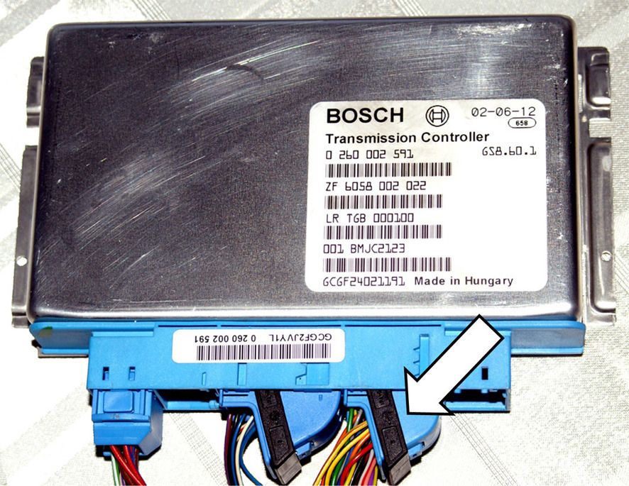
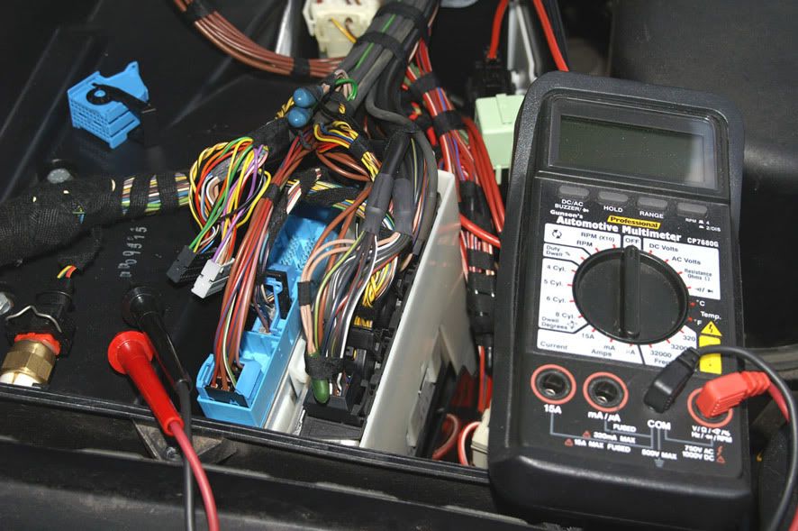
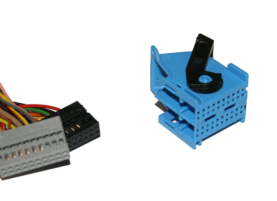
Another method of testing the switch, which doesnt involve crawling around at the back of the engine, is to check the continuity at the transmission ECU itself. This is more fiddly but has the advantage that it also tests the integrity of transmission wiring loom at the same time. The relevant pin numbers at the C1835 40-pin connector are
+ve = pin 31 (green wire)
L1 = pin 34 (black wire)
L2 = pin 24 (orange wire)
L3 = pin 14 (purple wire)
L4 = pin 4 (yellow wire)
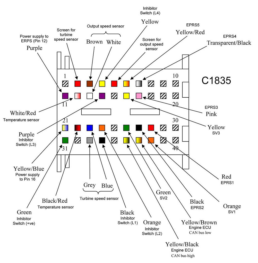
(Please note that this information applies to the ZF 5HP24 only and not to the GM 5L40-E)
+ve = pin 31 (green wire)
L1 = pin 34 (black wire)
L2 = pin 24 (orange wire)
L3 = pin 14 (purple wire)
L4 = pin 4 (yellow wire)
(Please note that this information applies to the ZF 5HP24 only and not to the GM 5L40-E)
")