Jimmy,
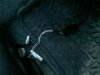
Not too sure what you are looking at. For the EAS, the manual I have shows a 5 pin connecter, but with only 4 pins in use. In post 10 above, there is a picture of the 14CUX connector I got confused over; showing only 3 pins in use. The EAS and 14CUX connectors are the same shape. The differences are:
connector.......EAS..............14CUX
colour............black.............white
pins...............4..................3
My RR is a 93 LSE, so there may some difference to your 94, but I'm told not.
Neil
p.s. Just in case. The EAS and 14CUX are under the right hand seat (drivers in the UK). Under the left hand seat is a blue ABS connector, different shape though.
")