Disco 4 (LR4) Can anybody check Gap IID for me please?

This site contains affiliate links for which LandyZone may be compensated if you make a purchase.
Just had a response from Gap "there's no need to code a heated steering wheel, it's a hardware fit only". Even more ****ed off now to be honest and don't understand why there are two options for it if you don't need them.

They also suggest that I need to set the DRL function to Scandinavian which is "Always on" but I'm guessing that will mean the headlights are always on which isn't what I want either.

I can do all the calibration for the suspension etc with my other diag tool which isn't VIN locked and has proven itself time and again with my L322 even down to sunroof calibration so I can't get past how much money I have wasted on this tool this week. Someone make me an offer!

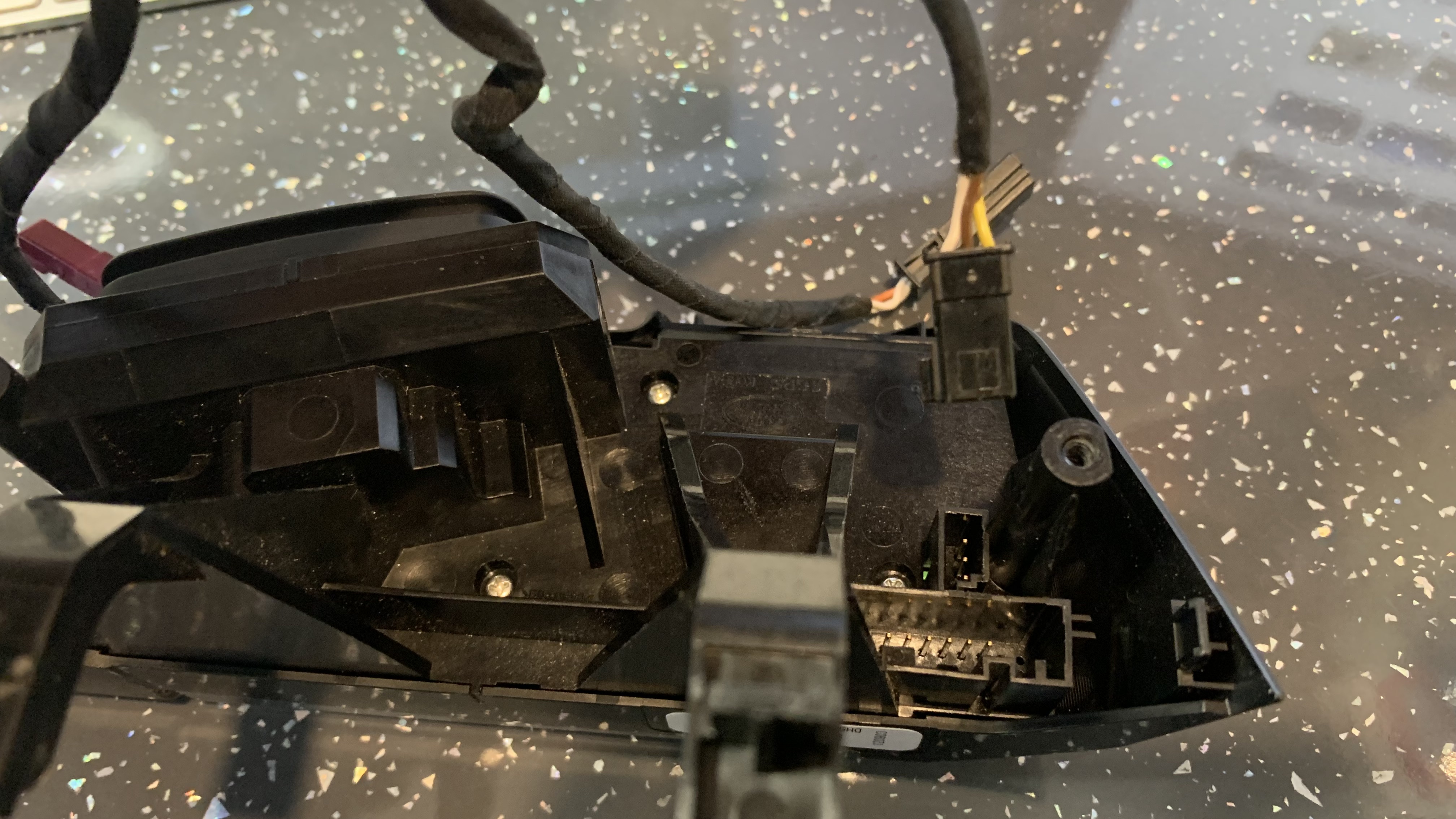
I've already proved the loom continuity as well as the switch gear
I got fault codes yes, but for a DAB antenna so I'm not counting that towards this issue.
 
Just had a response from Gap "there's no need to code a heated steering wheel, it's a hardware fit only". Even more ****ed off now to be honest and don't understand why there are two options for it if you don't need them.
Seems that the diagram was accurate then and there's no interface between the steering wheel heater unit and any programmable unit, all i can presume is that the options are there for the BMS to "know" that an additional load is present on the vehicle which can be relevant for the battery management at a point
 
Also very confused , ,

as it’s also been bugging the hell out of me have spent several hours trying to find more information , see there are 2 x different ECU’s along with 2 x types of looms which are year dependant

so thought if we can identify what ECU u have that will ensure if it’s correct or not and at the same time could always do some further tests ref voltages and resistance
 
Last edited:
I'm done sulking about it now. Mrs H has walked to work today so the car is here, I'll sack off a meeting at some point and swap the wheels back over then strip it and get the part numbers. With the wiring diagram I have and a test rig, I should be able to power the module as the car would and then meter the connections or jumper across the switch to prove the unit. Only concern is that if the car can't do it and it's not a faulty switch then I'm in for limited success myself.

Next round of investigation will commence shortly.

And thank you all for your efforts on my behalf.

no probs and indeed understand the frustration, - when I first bought mine I had an airbag fault , took me weeks to find everything that was wrong , involving taking out the headlining , half the dashboard , seats and carpet , felt like I was loosing my mind , so line many of us here really feel for u and hopefully we can pin the fault down for u

so I spent the last several hours as it was also bugging the hell out of me , think I may have found some more information for u which fingers crossed may save u some time

this is the first bit of info I found

NOTES

with the air bag off, remove the connector for the steering wheel element and check voltage with a multimeter for DC 12 volt. Press the on button, and see what happens. It may error out, and you'll have to probe the connector with it still connected to the heating element. But checking voltage would be first step.

You will also want to check the resistance in the heating element. On the wheel's connector, probe the power wires for resistance and if it is 0, the wheel is burnt out..it should be around 3.5 ohms.

You can also check for resistance in the temperature sensor, however this changes depending on how warm the area you are testing in is. I would say anywhere from 9-16 kiloohms depending on where you are. About 12-15 for room temperature .


————

also found some pictures showing the old and new ECUs , looks like the MY14 won’t work on earlier models , so need the old ECU which is in the picture plus what the looms look like

really hope this helps in order to get it working for ur beloved

upload_2023-1-19_9-45-8.png
 
Well that’s all I’ve been able to find so far , fingers crossed mate and indeed plse let us know how u get on , thks
 
I definitely have the later module. Stuck in meetings currently but I have swapped the wheel over. I'll strip it down this afternoon.

I don't really understand why the newer one won't work if there is no coding required, what would be the issue? Am I missing something here? It's a two wire self-contained system...

Considering whipping the one out of my L322 to see if that is the earlier type, I can live without it if I can swap the ECU for now and find one later to replace mine.
 
Hi

from what I can gather from the multitude of reading that there was a canbus speed change in 2014 , therefore the later module was fitted

definitely a minefield that’s for sure and like ur good self also spent hours trying to find as much info as possible

hope u have a good day and indeed fingers crossed the earlier one will work
 
Just found something else , person opened up one of the earlier modules, surprised to see the L322 marking on the board , plus found a picture where the RH switch modules horn at the bottom is either black or white

don’t make it easy do they

Plus fingers crossed and really hope at the end of the day this is useful to u

upload_2023-1-19_11-27-39.jpeg
 
Last edited:
Can you point me at your resource for this please?

Surely there are only two logical paths for this:
1, As suggested by GAP and others including the diagrams, it is a 2 wire connection and fully self contained. It doesn't talk to the CANBUS and therefore should work if all components are operational.
2. It does talk to the CANBUS and then there is a need to match the module to the vehicle which would then need to be coded and It will not be possible to bench-test without the CAN signal
 
Starting to make a bit more sense of this now.
I've stripped the wheel down and yes, I definitely have the later module. The later one appears to have CANBUS connections over to the LH switch pack. I now theorise that this is expecting an input from the CANBUS which as GTStuart has suggested is at a different speed to our car, it will never receive or be able to interpret such a signal and therefore is unlikely to actually turn on the heater function.

Next step in this arduous process: Gut my L322 steering wheel and sacrifice the heater ECU for the greater good. That one should be the earlier type and not need to see a CAN signal. In theory, that will simply work however, I see a potential sticking point in the switch gear, will it be able to take the signal from the later switches? No, I don't know either but I expect I'll find out soon enough.

I mentioned to Claire that I was going to sacrifice my heated wheel for her and she responded "I should bloody well think so!" isn't she the greatest? She then followed up with "and what will happen if I need to drive your car?" I'll have to quickly get another ECU to reinstate my heater I guess.

We should probably rename this thread at some point if I ever get this resolved in case it helps anybody later down the line.
 
My L322 has donated its heater ECU for the wheel but now I need to change the wiring connector and extend the harness slightly. I'm relatively confident this will work as long as I know which is which. Can anyone provide me with this info please?

This is the plug and switch pack for the Disco. I need to connect the 3 pin black plug to the L322 ECU below
IMG-6528.jpg


The purple plug needs to be replaced with the black on from above but I don't know the wiring colour layout on the plug. Do any of you lovely people have a picture of the Discovery ECU and wiring plug that I can copy?
IMG-6529.jpg
 
Hi mate

good to see you’ve made some progress , is the wiring diagrams above any good to u or do u need the L322 wiring as well and can find that as well if u need it

am just checking a few things for u and will update u as soon as I find them,
 
Appreciated as always, but as good as this is, it doesn't tell me which way round the wires go in the steering wheel connector. That's where I'm stuck right now.
 
Back
Top