Neptune19522
Active Member
- Posts
- 111
- Location
- Warwick
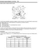
Got the same set of figures - not exactly the same but all in the same area - with or without the MAF connected. Not sure if it is me or hopeful thinking but the crank to throttle authority time seems to be reducing. The engine is still ' cold' so I would expect some delay as it changes from starting map to running map. Only if driving could I be certain that the changes we are effecting are having any effect.
Concerned about the Nanocom in that several times it comes up blank figures until I unplug and reconnect with ignition on. There is also a new window on boot up complaining about 'no firmware'. I did have a 64G SD card in it but it complains of having no SD card. I did try to initialise it on my old laptop which is still running Microsoft OP. The speed from which it recorded a 'disc initialised' was far too quick. I am planning to get a much smaller SD card soon!
Concerned about the Nanocom in that several times it comes up blank figures until I unplug and reconnect with ignition on. There is also a new window on boot up complaining about 'no firmware'. I did have a 64G SD card in it but it complains of having no SD card. I did try to initialise it on my old laptop which is still running Microsoft OP. The speed from which it recorded a 'disc initialised' was far too quick. I am planning to get a much smaller SD card soon!