Datatek
Well-Known Member
- Posts
- 45,015
- Location
- Near Poitiers SW France
This is for RangeRoller dt and anyone else who thinks it may help with starting the diesel.
I had a spare hour yesterday while testing a bit of kit I repaired so I had a look at adding a diode to an early fuse box to operate the lift pump whilst cranking as is the case with later fuse boxes. Please bear in mind that there are several versions of the fuse box, so testing per #5 is important.
Items needed to do the mod, Philips screw driver, Solder, soldering iron, file and a 1N4005 diode. I can supply the diode if required FOC.
There are 7 photo's.
#1 Shows schematic with D4 as fitted on later fuse boxes.
#2 Shows schematic with D4 missing on the early fuse box.
#3 Shows the relays that need to be removed to access the fixing screws including Relay
16, the hardest part is getting the assembly out of the housing. I use 2 thin metal strips
pushed in on the long sides to hold the latches back, then the short sides can be held
back with fingers while the PCB's are eased out.
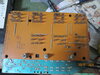
#4 Shows where a wire needs to be inserted in the Relay 16 socket for testing.
#5 With a meter on Ohms connect one lead to the test wire and with the other verify where
P1 C575 is. (Relay 16 pin 5). On this 1996 fuse box it is at the position marked by 2 red triangles.
Also shown are the 2 existing diodes D2 & D3.
#6 Shows where to file a small groove for the new diode wire, this provides support and
makes it easier to solder to the pin.
#7 Shows the new diode fitted. Make sure you get the diode the right way round, white
band end goes to the existing diode. A spot of silicone or super glue can be used to
ensure the diode is secure.
I had a spare hour yesterday while testing a bit of kit I repaired so I had a look at adding a diode to an early fuse box to operate the lift pump whilst cranking as is the case with later fuse boxes. Please bear in mind that there are several versions of the fuse box, so testing per #5 is important.
Items needed to do the mod, Philips screw driver, Solder, soldering iron, file and a 1N4005 diode. I can supply the diode if required FOC.
There are 7 photo's.
#1 Shows schematic with D4 as fitted on later fuse boxes.
#2 Shows schematic with D4 missing on the early fuse box.
#3 Shows the relays that need to be removed to access the fixing screws including Relay
16, the hardest part is getting the assembly out of the housing. I use 2 thin metal strips
pushed in on the long sides to hold the latches back, then the short sides can be held
back with fingers while the PCB's are eased out.
#4 Shows where a wire needs to be inserted in the Relay 16 socket for testing.
#5 With a meter on Ohms connect one lead to the test wire and with the other verify where
P1 C575 is. (Relay 16 pin 5). On this 1996 fuse box it is at the position marked by 2 red triangles.
Also shown are the 2 existing diodes D2 & D3.
#6 Shows where to file a small groove for the new diode wire, this provides support and
makes it easier to solder to the pin.
#7 Shows the new diode fitted. Make sure you get the diode the right way round, white
band end goes to the existing diode. A spot of silicone or super glue can be used to
ensure the diode is secure.
Attachments
-
 D4 Fitted later fuse box.jpg218.9 KB · Views: 148
 -
 D4 Missing early fuse box.jpg211.3 KB · Views: 162
 -
 Fuse box mod001.jpg470 KB · Views: 165
 -
 Fuse box mod002.jpg477.1 KB · Views: 189
 -
 Fuse box mod003.jpg591.2 KB · Views: 168
 -
 Fuse box mod004.jpg376.8 KB · Views: 145
 -
 Fuse box mod.jpg270.4 KB · Views: 156
