P38A A series of faults

This site contains affiliate links for which LandyZone may be compensated if you make a purchase.
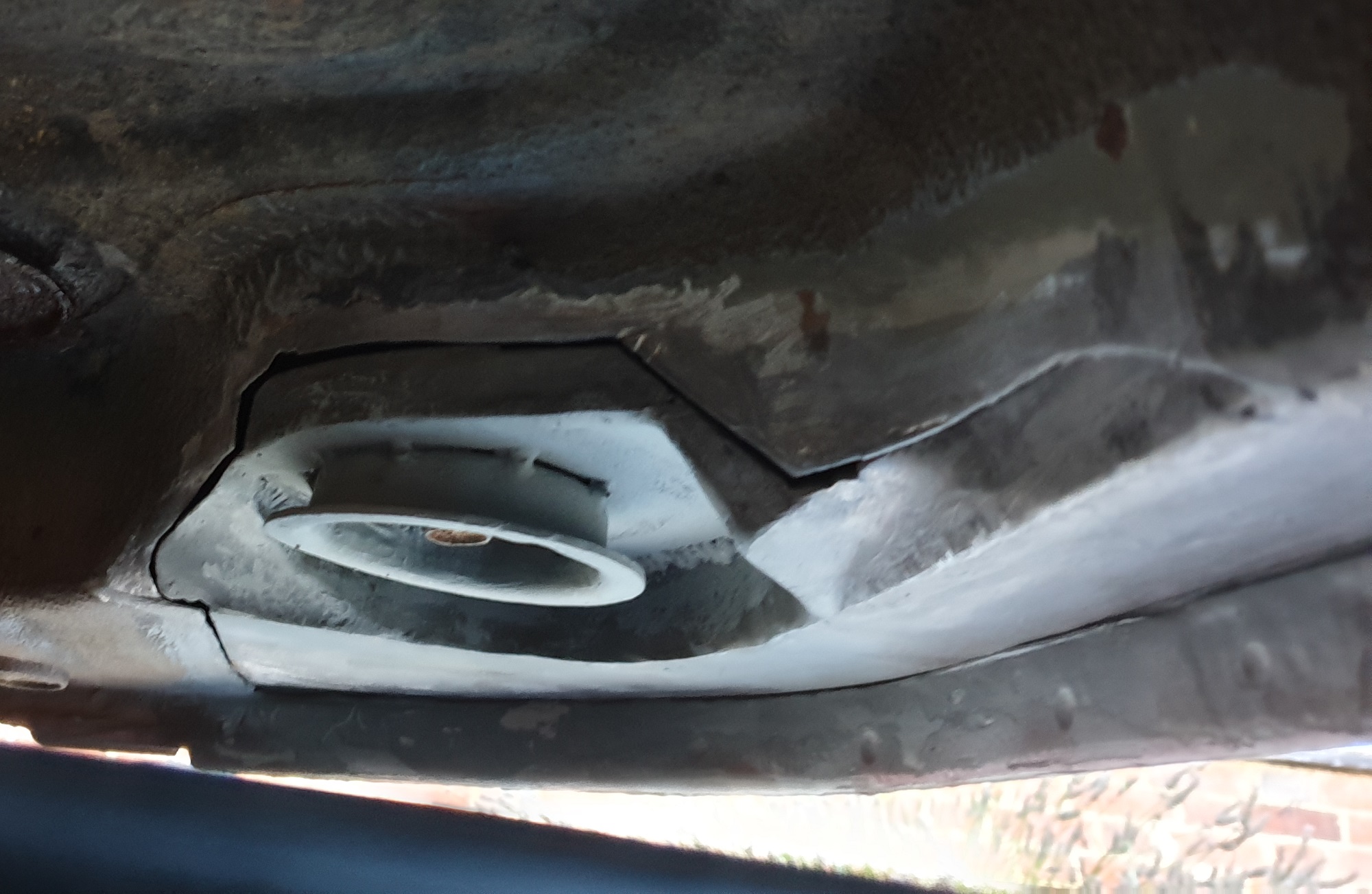
Yup, very similar games on Subaru cam covers which are lots of fun if you try to replace the seals with the engine still in the car...there's about two inches between each cover and the chassis leg...

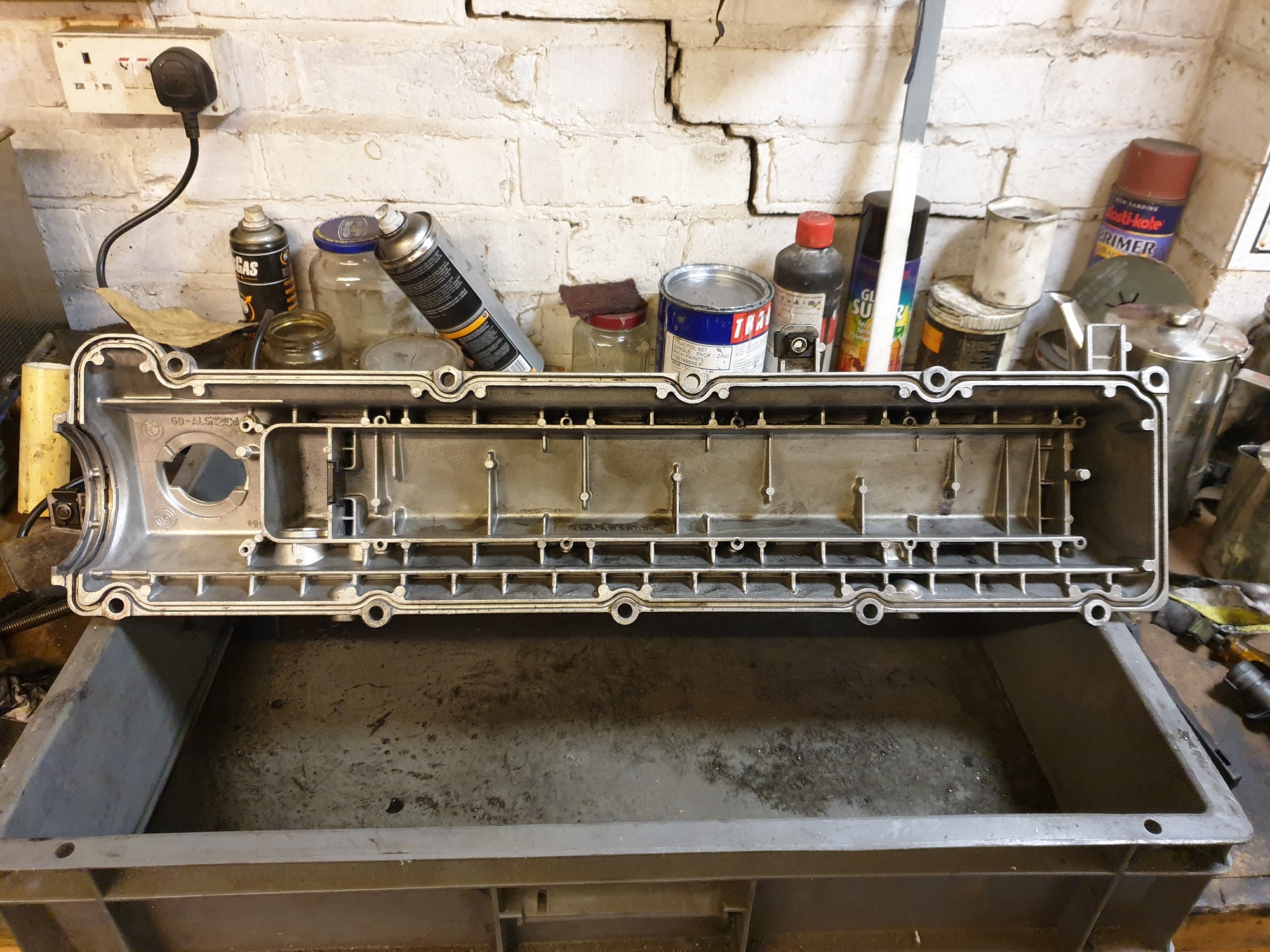
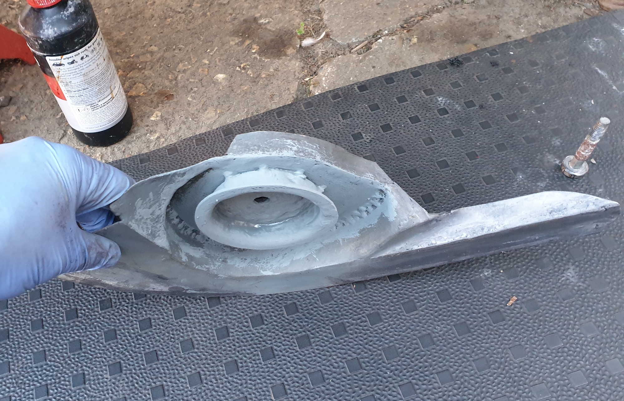
I've RTV'd the whole seal to the cover in an attempt to make things easier
 
And back to adding pics.
The rocker cover all stripped down and black sludge removed:
c5N8ID4.jpg


The mesh filter cleaned of sludge refitted with the cleaned up baffle plate waiting to be refitted:
4ZN391f.jpg


Baffle plate bolted back in with loctite'd screws and new seal RTV'd in place:
XGgtcHg.jpg


And then the modified bonded (RTV again) and screwed in place breather vent:
1TaPMEY.jpg


The screws are are M4x0.75 and clocked the way they are as those were the only positions where there was enough meat on the casting where I could drill and tap it

Rocker cover is now back on the engine, seal seamed to go in ok, and torqued down
 
Now going back in time to where I left it before drying up for a bit...

I had a lovely time cleaning up the transmission cooler and refitting the mud guard where all the mounts for it were broken. Thankfully I have a Rivnut tool, ratchet type not pop-rivet.

GH4ZNFt.jpg


s0LEepP.jpg


L6XRkYk.jpg


P5jpxdD.jpg


jXwSbkh.jpg


Slight curiosity while I was under the rad-pack area cleaning up was finding these connections with nothing attached:

C7Gt7t0.jpg


Clearly some kind of cooler built into the rad, but not optioned on mine, or has been removed; any clues?
 
Gave the hub carriers a bit of a clean and lick of paint:

Bzaz5iX.jpg


Py8s75S.jpg


E06Hd6N.jpg


And new shaft seals too.

Knocked up my own alignment tool to centre the hub carriers with the shaft centre having fitted new ball joints top and bottom each side using the bearing housing bolted in but no shaft:

UGGEN1a.jpg


xVYt9qk.jpg


Sockets were a perfect fit inside the spline of the hub and centre of the axle casing
 
Driveshafts refitted:

Rbz8A1s.jpg


ABS sensors refitted after the 'inserts' thoroughly cleaned and ceramic grease used to lube them:

uyQDa7o.jpg


yjP8qQF.jpg


xDuMb6M.jpg


Managed to loose the ABS sensor cable bracket for the OSF so fabbed a new one for it from some stainless sheet that I had knocking around:

FWATHla.jpg


Naturally I've found the thoroughly cleaned and de-rusted original since

New drag links and ball joints for the steering:

XRVJJDn.jpg


CJAdlao.jpg
 
The disc backplates have had a Christmas too and have been repainted, but just to show the effects of Bilt Hamber Deox-C here's a half and half sequence showing how well it removes the rust:

XmmmK8P.jpg


kmq2sIK.jpg
 
And now we come to the horrors lurking at the back on the near side rear of the car behind the bumper, mud guards and arch liners, discovered while being me and cleaning the chassis off and giving it a wipe down with ACF50 and my hand disapeared into the car:

4fZU5aY.jpg


Near side rearmost bodymount wasn't well

To get to it and make a decent repair I had to undo all the body mount bolts, but only remove the ones from the nearside. I then made up some inch thick spacers from polyethylene bolted together in pairs to slip above body mount rubbers when I jacked the body off the chassis, which, once the rear rubber was removed giving me a fair bit of clearance: to get cutting out the rot and welding:

91cENk3.jpg


PkOCIUN.jpg


89caz4s.jpg


dFKY0cp.jpg


Sea9RoW.jpg


Pdo0kN6.jpg


MDVeDeJ.jpg
 
With the rot cut out (there was a lot hiding behind the rubberised underseal) I made a template from card to make up a complete repair panel:

Xv7ukJX.jpg


Frj9dl9.jpg


The repair panel was fabricated from 1.5mm thick sheet steel, it was never intended to be a perfect piece to look like a pressing, just something to return the strength back to the rotted out corner and fit what was left. For the 'cup' for the body mount rubber I got lucky in finding a coil spring seat in my pile of bits of metal that might come in useful, pressed from 3mm plate a bit of cut and shutting and I think it came out well. That and the salvaged cotton real spacer for the inside and it all came together:

a27DxJD.jpg


oQY29w7.jpg


5H53Uth.jpg


nqAs9pI.jpg


yUwL7vR.jpg


Acej82g.jpg


Liberal coating of Polyeurthane Zinc loaded primer on the inside away from the weld points, and then weld through primer for the bits that were going to get welded
 
Epic body repair kiddo. Looks smart and strong.
:cool:
One thing I'll add is that the cv joint needs loctite on it when it goes into the hub. They start to clock after a while. My rears were doing this and after undoing the hub/shaft nut I found rust dust..... Cleaned it out and poured loctite on the splines and gently blew it in along the splines. Not exactly how it should be done but it worked on the rear. :)
 
Now going back in time to where I left it before drying up for a bit...

I had a lovely time cleaning up the transmission cooler and refitting the mud guard where all the mounts for it were broken. Thankfully I have a Rivnut tool, ratchet type not pop-rivet.

GH4ZNFt.jpg


s0LEepP.jpg


L6XRkYk.jpg


P5jpxdD.jpg


jXwSbkh.jpg


Slight curiosity while I was under the rad-pack area cleaning up was finding these connections with nothing attached:

C7Gt7t0.jpg


Clearly some kind of cooler built into the rad, but not optioned on mine, or has been removed; any clues?

The manual gearbox doesn't have an oil cooler but flows through the bottom of the rad.
 
Epic body repair kiddo. Looks smart and strong.
:cool:
One thing I'll add is that the cv joint needs loctite on it when it goes into the hub. They start to clock after a while. My rears were doing this and after undoing the hub/shaft nut I found rust dust..... Cleaned it out and poured loctite on the splines and gently blew it in along the splines. Not exactly how it should be done but it worked on the rear. :)

I think that loctite tip was in the manual as it's not the first time I've heard it and that I did do it...final torquing of the nuts is waiting for the moment I get the wheels back on.

There's more welding/fabrication madness to come ;)
 
Cheers, the photo's don't really show just how awkward it is to get into that corner to weld either, while it's not the pretiest I do know that what I've put in is good and strong!

In accessing the body mount and to make sure there weren't any other horros lurking round that area I decided to remove the rear bumper. I already knew from looking in there with a torch that there wasn't much left of the bumper support in the corners, but as the bumper was mostly attached I was ignoring it, sadly in removing the bumper I was going to have to make repairs. This was what was left of the section bonded to the inside of the plastic bumper:

8g9HnBX.jpg


HsI6Et1.jpg


And the remains of the brackets in the chassis that I had to cut the bolts off to remove:

8oQHucX.jpg


sxIwNLM.jpg


With the brackets removed the chassis ends came up well after a bit of wire brush and Jenolite attention:

u3WzbDj.jpg


emWT6N2.jpg


I did the same to the removable tow bar crossmember but didn't take any pics before it, and the chassis ends got a coat of my Zinc loaded primer and truck bed paint:

x3jLSpR.jpg


01Mzdit.jpg


flEuFge.jpg
 
To replace the bumper support bar I got given a contact with a large sheet metal folding hydraulic press break and from an off cut of 2mm thick x 2300mm long plate had a channel folded up 100mm deep at the top, 90 degree (inside) bend into 115mm tall vertical then a 105 degree (inside) bend back to what ever was left (70mm I think it was, when the original was about 90mm) base. I worked out that with a small wedge cut out just inboard of the chassis legs I could fabricate something good enough to bond the bumper too and still clear enough of the fixed points.

This worked out, with having to fabricate new mounts for the chassis (I wasn't going to pay 50 quid each for new ones!) and repairing the bolt on side brackets to be quite a mission but it ended up looking like this:

q519fuU.jpg


kiRwOsG.jpg


aPdFIzP.jpg


ENsUElp.jpg


V5Iupx7.jpg


vxvepcg.jpg


OcMRrkP.jpg


There's a fair bit of adjustment available to get the bumper pretty well aligned between the various brackets and the support. The channel has had a coating of the Zinc primer and truck bed liner pain on the outside, the inside is Zinc primed and coated in stone chip followed by flat black.

I still need to take some pics of the repaired side brackets, fabricated chassis brackets and what's left of the brackets that attach the bumper sides to the chassis

And that brings everything up to date!
 
Back
Top