border
Well-Known Member
- Posts
- 3,609
- Location
- North East. UK
OK Really sorry for not stating which engine I have or for changing my Profile. My Disco is a 2 door R Reg,. 300Tdi had quite a few modifications for Off-roading by the PO, I just wanted a normal Discovery for the winter, but seen a lot that were full of rust, and needed lots of welding aswell as other work, this One is really good with lots of new parts, suspension ect, so couldn't refuse it.
Just sorting out a few problems along the way.
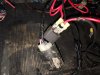
Anyway back to this Problem. Will try new Relay and Just hope that's all it is. Could it be possible that I have the connectors on the wring spades on my Relay ? Do they have to go on certain Order ??
Just sorting out a few problems along the way.
Anyway back to this Problem. Will try new Relay and Just hope that's all it is. Could it be possible that I have the connectors on the wring spades on my Relay ? Do they have to go on certain Order ??
Attachments


Last edited:
")