You are using an out of date browser. It may not display this or other websites correctly.
You should upgrade or use an alternative browser.
You should upgrade or use an alternative browser.
Another Electrical Problem
- Thread starter border
- Start date
This site contains affiliate links for which LandyZone may be compensated if you make a purchase.
border
Well-Known Member
- Posts
- 3,620
- Location
- North East. UK
I'm trying to put the Wiring Right Mate . I know it is a Mess at the Moment. Which is why I'm asking advice. Not comments about the state of it.With that wiring, I wouldnt assume anything...
- Posts
- 48,277
- Location
- East Dorset
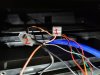
@border, do yourself a favour and get a meter! They are cheap as chips and remove the guesswork! A long long time ago, in house wiring, red was live and black was neutral. Earth I think was green pre 1977, then became green/yellow. In low voltage stuff, DC like torches and the like, and in meter probes this has continued, but as far as car wiring is concerned different manufacturers had and have their own preferred colours. Some have been standardized but they are not as obvious as you might like. A quick glance at any wiring diagram will show this, although brown wires tend to be live and black wires tend to be earths. You might be right, the wally who wired this lot in may have chosen to wire it in with black for negative (Earth) and red for live, there is a bit of logic in that, but you cannot be sure.Thanks. Need to get an ohm-meter, with a continuity tester probe thingy, The Black wire number 2 in pic Lights it up, there is nothing on the Red nember1, so does that mean that my Black is Live. Now I would have thought that Black was Earth and Red was Live. But maybe not in this case ??
Be very careful with instruments, they definitely do not like being wired the wrong way and of course there will always be a signal wire from a sensor and a wire to the illumination bulb. So for each instrument you may well find 4 wires. It is a long time since I wired an instrument panel so others may jump on and point out things that may have changed. For instance many instrument panels now have circuit boards which complicates things much more. and I haven't even mentioned voltage regulators!
border
Well-Known Member
- Posts
- 3,620
- Location
- North East. UK
Yes mate, I know... Im an electrician, so I agreed I wouldn't assume Red is positive, and black is ground (-ve)
OK sorry Mate. Just looking for advice on how to get it back up and working. Cant afford to get garage to do it. also like solving problems myself from asking questions.
Im3 thirds of the way through a 11O Rebuild done all alone with help and advice from members on here.
Unless as Stanleymaster said some Wally might of wired it that way, obviously the wrong way.
Im3 thirds of the way through a 11O Rebuild done all alone with help and advice from members on here.
Unless as Stanleymaster said some Wally might of wired it that way, obviously the wrong way.
Will find a meter tomorrow Mate and check which one is Live and Earth . Then ask how to wire them in to Ignition.@border, do yourself a favour and get a meter! They are cheap as chips and remove the guesswork! A long long time ago, in house wiring, red was live and black was neutral. Earth I think was green pre 1977, then became green/yellow. In low voltage stuff, DC like torches and the like, and in meter probes this has continued, but as far as car wiring is concerned different manufacturers had and have their own preferred colours. Some have been standardized but they are not as obvious as you might like. A quick glance at any wiring diagram will show this, although brown wires tend to be live and black wires tend to be earths. You might be right, the wally who wired this lot in may have chosen to wire it in with black for negative (Earth) and red for live, there is a bit of logic in that, but you cannot be sure.
Be very careful with instruments, they definitely do not like being wired the wrong way and of course there will always be a signal wire from a sensor and a wire to the illumination bulb. So for each instrument you may well find 4 wires. It is a long time since I wired an instrument panel so others may jump on and point out things that may have changed. For instance many instrument panels now have circuit boards which complicates things much more. and I haven't even mentioned voltage regulators!
- Posts
- 48,277
- Location
- East Dorset
To be absolutely and completely honest, I'd find the live feed to all of this, the live feed to the instrument lights, the individual sensors for each instrument and a good nearby earthing point. Then I'd rip the existing wiring out and rewire it properly with good soldered connections covered in shrinkwrap and each connection tested with an ohm-meter to make sure I made a good joint, making new crimped connections to the instruments where appropriate. I have wired a few kit cars and they all have individual instruments. And older ones needed a voltage regulator so that the instruments read consistently and didn't tell you you had fuel when you didn't. I would also try and follow the existing wiring colours from the vehicle manufacturer and I would do this either by using the existing loom from the donor vehicle or by buying a loom from a scrapper and using that to extend wires that need it. Then you can relate it all to the original wiring diagram or one you draw for yourself.
But I have come across kit cars that were all wired in the same colour!
As soon as you start wiring in extra instruments, C/Bs , fans, Spot/driving lights etc, you are in this realm. It ain't rocket science and you can use additional safety measures like wiring items that use a lot of juice, like fans and horns, in so that they are continually fed positive and the switch is in the negative to earth wire. And DO use relays.
I'm not an electrician, by any means, I just have a bit of experience on older style cars, but as we have electricians in our midst I expect they'll jump on eventually and say stuff. But meanwhile try to be as logical as you can and start from the basics, make no assumptions and test everything. Take your time and don't go jumping about all over a bunch of wires that look like dog's spaghetti!
Yes, the front additional fog lights on my Disco were ALL wired in Brown 1.5mm brown singles cable.. I think thats all the PO had... I ripped it all out and rewired the relay with appropriate coloured cables, with heat shrink on the connections.
Colthebrummie
Well-Known Member
- Posts
- 9,870
- Location
- Thatcham
Just to emphasis what stanleysteamer said, don't put a multimeter probe set to ohms on a live wire else you might cook the meter. Always have the meter set to volts before any test, then if no voltage is measured, you can set it to resistance (ohms)
Col
Col
- Posts
- 48,277
- Location
- East Dorset
Thanks Col, should have made that clearer!Just to emphasis what stanleysteamer said, don't put a multimeter probe set to ohms on a live wire else you might cook the meter. Always have the meter set to volts before any test, then if no voltage is measured, you can set it to resistance (ohms)
Col
border
Well-Known Member
- Posts
- 3,620
- Location
- North East. UK
- Posts
- 48,277
- Location
- East Dorset
Happy for you, but do try, perhaps with your mate, to wire the blower through a relay.Just an update on this.
A Mate came and wired these 2 to the Ignition, all dials Lit up again and Gauges working as they should.
Tidied up the wires a bit, but they do need doing up properly to make them safe.
Ready for my next Fix now
border
Well-Known Member
- Posts
- 3,620
- Location
- North East. UK
Will Do Mate. Cant understand why it stopped on the Relay, as I did try Brand New one to. Will connect it back up again, never know it might just work again, with the dials been back on.Happy for you, but do try, perhaps with your mate, to wire the blower through a relay.
Colthebrummie
Well-Known Member
- Posts
- 9,870
- Location
- Thatcham
Maybe but I wouldn't let you do it to mine.Sticking 12 volts up the leads of a meter set to resistance wont damage it...
Col
I stick 240 up mine most days accidentally.... never harmed it. Never busted a meter doing that in 36 years of being a sparky..Only issue you may get is if you do it on current, as it may pop the fuse. They are made to withstand issues such as this.
Colthebrummie
Well-Known Member
- Posts
- 9,870
- Location
- Thatcham
I once accidentally measured the resistance of the mains on a very, very expensive Avo which I had borrowed from work, it completely knackered it.
Col
Col
Similar threads
Discovery 1
3 door 300tdi commercial
- Replies
- 24
- Views
- 3K