Bounty
Well-Known Member
- Posts
- 276
- Location
- Cheshire, United Kingdom
What you need:
Freelander 1 - Facelifted (2003 - 2006, any trim, any platform [XEi, XDi, Td4, V6])
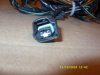
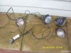
x1 JTF000180

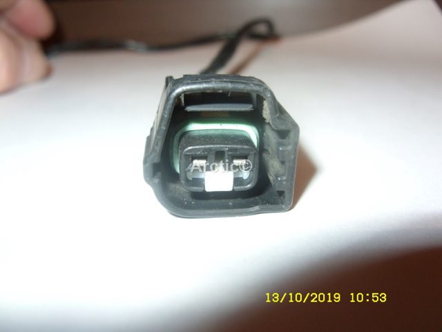
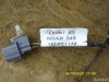
x1 Temperature sensor connector from a Rover 75/MG ZT

x1 Omnitec T4 Testbook on RDS v6.0.0
x1 T4 Freelander Disk DTL35X
What you do:
Part l - Hardware
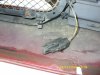
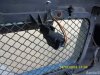
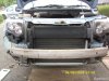
Drop the bumper by unscrewing just about everything under the sun from the wings, across the front grille and anything else it can hang onto. Just behind the bumper bar on the offside you'll find a small plastic rail which will accept your JTF000180 sensor; attach it there.


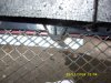
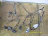
Attach the wiring to the sensor and run it up into the engine bay, then across the radiator and back to the fusebox. At the back of the bay there are some rubber gromits - one leads to a position just under the glovebox. Make the smallest puncture possible to thread the cables through. Once those are through you can replace the bumper.
Optional: Add some conduit over the wires to protect them from the weather.
Remove the instrument pack by disassembling the shroud: three screws hiding at the top which lower to deconstruct the retaining ability and then will allow the pack to slide forward and out.
Thread the cables however you wish through the dash until they meet the instrument pack. I went behind the blanking plate atop the glovebox and across the cup holders then in through the side of the instrument shroud.
On one side of the pack is a crimson plug that can be carefully removed. Within the armour will be a series of numbered plugs - among them is pin #18 which may or may not be occupied. If it is not you will have to find a way to connect one of your wires with a spade into the slot. If it's occupied you can snip the existing wire open and solder in the new connection.
You'll notice you have another wire, this is the earth. Attach it to wherever you feel is best. For me this was just under the steering column against a bolt.
Reassemble your instrument pack.
Part ll - Firmware
With your T4 operator running the correct versions you can plug in to your car. Under "vehicle diagnostics" you'll find the 'LCS Coding' option, within that will be a single-toggle "IPK Temp" option which will likely read "Disabled". Tap it to set it to "Enabled" then press continue. Follow the T4's instructions and at one point when turning the key to position 2 you'll know that you succeeded if the temperature flickers up but ensure you continue the process until completed. If you are asked for your VN number, it is inside of the passenger door.
If you do not receive anything within the temperature slot, the T4/Disk versions are not compatible with this upgrade.
Your temperature may read one of two states: if the sensor hasn't been connected for long enough, or is not connected properly, you will receive a reading of -30ºC. If it has, it will either be on it's way to the correct reading or already there. You can now use the left stick in the instrument to flick between the two units of measurement, ºC or ºF. A snowflake will also be displayed under a higher limit between 3ºC and 4ºC.
Be cool and have a chill day.
With thanks to:
LRUK for the technical manuals
@Arctic2 for the MG ZT connector
Discount MG Rover Spares for the sensor
Lovell - LRUK for use of his T4
Freelander 1 - Facelifted (2003 - 2006, any trim, any platform [XEi, XDi, Td4, V6])
x1 JTF000180
x1 Temperature sensor connector from a Rover 75/MG ZT
x1 Omnitec T4 Testbook on RDS v6.0.0
x1 T4 Freelander Disk DTL35X
What you do:
Part l - Hardware
Drop the bumper by unscrewing just about everything under the sun from the wings, across the front grille and anything else it can hang onto. Just behind the bumper bar on the offside you'll find a small plastic rail which will accept your JTF000180 sensor; attach it there.
Attach the wiring to the sensor and run it up into the engine bay, then across the radiator and back to the fusebox. At the back of the bay there are some rubber gromits - one leads to a position just under the glovebox. Make the smallest puncture possible to thread the cables through. Once those are through you can replace the bumper.
Optional: Add some conduit over the wires to protect them from the weather.
Remove the instrument pack by disassembling the shroud: three screws hiding at the top which lower to deconstruct the retaining ability and then will allow the pack to slide forward and out.
Thread the cables however you wish through the dash until they meet the instrument pack. I went behind the blanking plate atop the glovebox and across the cup holders then in through the side of the instrument shroud.
On one side of the pack is a crimson plug that can be carefully removed. Within the armour will be a series of numbered plugs - among them is pin #18 which may or may not be occupied. If it is not you will have to find a way to connect one of your wires with a spade into the slot. If it's occupied you can snip the existing wire open and solder in the new connection.
You'll notice you have another wire, this is the earth. Attach it to wherever you feel is best. For me this was just under the steering column against a bolt.
Reassemble your instrument pack.
Part ll - Firmware
With your T4 operator running the correct versions you can plug in to your car. Under "vehicle diagnostics" you'll find the 'LCS Coding' option, within that will be a single-toggle "IPK Temp" option which will likely read "Disabled". Tap it to set it to "Enabled" then press continue. Follow the T4's instructions and at one point when turning the key to position 2 you'll know that you succeeded if the temperature flickers up but ensure you continue the process until completed. If you are asked for your VN number, it is inside of the passenger door.
If you do not receive anything within the temperature slot, the T4/Disk versions are not compatible with this upgrade.
Your temperature may read one of two states: if the sensor hasn't been connected for long enough, or is not connected properly, you will receive a reading of -30ºC. If it has, it will either be on it's way to the correct reading or already there. You can now use the left stick in the instrument to flick between the two units of measurement, ºC or ºF. A snowflake will also be displayed under a higher limit between 3ºC and 4ºC.
Be cool and have a chill day.
What you need:
x1 Freelander 1 facelift
x1 JTF000180
x1 Temperature sensor connector from a Rover 75/MG ZT
x1 Posi-head screwdriver
x1 Omnitec T4 Testbook (MUST be the T4)
What you get:
External temperature reading above the odometer that can switch between ºC and ºF. It even displays a snowflake if it's cold enough.
Foreword:
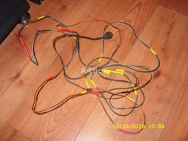
I am going to preface this guide by saying that if you are unable to get a hold of everything required then it will be impossible to make this modification. The hardest part to get out of the lot is the connector, and at that you may have to get a hold of the complete loom in order to fish out the bit you need. If you don't have both physical parts in your hands I highly discourage throwing money at enabling the reading; you'll forever believe it to be -30ºC outside and you won't ever want to get out of the car again. If on the other hand you can get a hold of all that you need then do read on.
What you do:
Part l: Prep
We can make life easier for ourselves with a few checks; firstly, make sure that the connector and the sensor marry. The click when they join will sound solid, and result in a waterproof connection that you'll find indispensible under the bonnet. Then invest in some conduit to go over your cabling, resulting in a much stronger cable running from the sensor to the binnacle.
You should also dial your local automotive shop to ensure they have the T4 unit; rare as they are it is the only diagnostic kit that will work for this operation. Thankfully being Freelander owners we can make use of any shop specialising in Rover/MG/Land Rover, so any of those are likely to store our coveted kit.
With these checks in place you'll find a much smoother ride to the finish.
Part ll: Hardware
It should be very obvious how the sensor fits within the connection; feel free to join the two when you have them. The first step is to find plenty of time to allow for your own experience in doing this job; first you're going to have to drop the bumper.

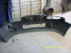
Your facelift bumper is a single piece from wing to wing, up to the bonnet and all the way down to the sump guard. Your first port of call should be beneath the wheel arches - you'll find several screws with washers lining the forward half of the arch. Unscrew these and look for additional screws in the opening between the wing and side panel. Once you've successfully freed these off then you should move under the car to the sump and find another set of screws across the bumper. Lastly you may or may not have another set of three just below your front license plate. With all of these gone you'll just have to unbolt the bumper from under the bonnet lid and it will come away. Put it down where it will not get scratched.
The elusive mounting rail sits on the right hand side of the car. It's a three-pronged piece of plastic which will accept your connector simply by having you slide it back over the forward-facing prong. This will capture your harness and forever more it shall sit. The next part of this is largely personal preference so thread your cable up inside the engine bay. I used a circular hole right behind the mount and threaded the cable through there.

Recommended: Within the engine bay I introduced some conduit over my cable to protect it from the elements and the engine itself.

With the now armoured cable I navigated it across the bay just below the cusp of the bonnet catch and around to the fusebox. For ease of access just unbolt the fusebox and move it slightly to enable you to perform this next trick; you'll need to locate a rubber grommit up against the passenger's side footwell. With the tiniest nick you should be able to pass your connection through to beneath the glovebox. If you've extended your connection you may consider disconnecting it and joining the two once you're inside the cabin. If you do it this way you should find that your cable can run up and into the space above the glovebox.

From the other end you'll need to get at your instrument pack; you'll find around six screws hold it in place beneath the shroud and at the sides.

Once it's out, look around the back of the pack for a crimson tinted connection. It's fiddly; you'll need a pin, or even a ampmeter prod will do. Press in on the retainer and free the red connection from the instrument pack (IPK).
Within this connection you are looking for pin #18. The owner's manual describes it as a "Solid Orange" (SO) cable. You may or may not have one present already; if you do it's just connected and it will terminate within the centre console, rendering it useless. However if you do have it you've spared yourself some time as you'll need the spade connected to the existing cable. You can save yourself more of a headache by simply splitting the existing cable, then soldering your fresh wire into the existing connection.

To the left of the IPK you will find a hole that you can thread your cable through - it will snake it's way up to the cup holders and back across to where your engine bay cabling is behind the glovebox panel. Now you can connect the two, rebuild your glovebox and return your IPK to its shroud. Re-attach your bumper and close the bonnet. Hardware portion complete!
Part lll: Firmware
Unfortunately at this time, I've been so far unable to access this option properly. Two attempts later and no joy I've become wary of trying again due to the cost of having someone open up their unit and without the ability to experiment myself it's still an unknown entity within this process.

On the T4 kit you'll be looking firstly to set it up on the Land Rover disc, then select your vehicle as a Freelander (2001+). Within the first menu you're looking for the "Vehicle Configuration" option. Within this you'll look for a secondary set of menus. On the far right hand side you'll find an option called "LCS Coding". Within that menu will appear two pages worth of options. On page 2 you'll see one that says "IPK Temp" and it will either say "Enabled" or "Disabled". If it says disabled, tap it to set it to enabled and then along the bottom press "Continue" to enable it.
And that is unfortunately where this guide ends I'm afraid. That *should* have set up the IPK to display the initial configuration reading of -30°C... except it didn't for me. If it does for you, simply go on your merry way and watch in amazement as the temperature climbs up while the car adapts to its working range. If it doesn't then we're in the same boat - I don't know what other settings need to be enabled, set or switched to reach the finishing line. If you do however feel free to reply - we're all waiting with bated breath.
x1 Freelander 1 facelift
x1 JTF000180
x1 Temperature sensor connector from a Rover 75/MG ZT
x1 Posi-head screwdriver
x1 Omnitec T4 Testbook (MUST be the T4)
On top of having a T4 vendor, you must also ensure that the vendor is running the correct version of the T4 unit. For Land Rover this is RDS 6.0.0. MG/Rover typically use v5.0.6 for their servicing needs - but any garage may or may not have the ideal version for this. Call ahead of time and ask which version they are on. In addition they must stock the correct Land Rover diagnostic disc to load into RDS 6.0.0. For the Freelander 1 that disc's code is DTL35X. Without the perfect means of installation it is highly likely you'll be left with an incorrect validation string within your ECU and the IPK's VN number. If the T4 unit is improperly configured you are likely to enable the feature only to find that nothing is added to the LCD screen within the instrument pack even when the option is set to appear.
x1 Soldering ironWhat you get:
External temperature reading above the odometer that can switch between ºC and ºF. It even displays a snowflake if it's cold enough.
Foreword:
I am going to preface this guide by saying that if you are unable to get a hold of everything required then it will be impossible to make this modification. The hardest part to get out of the lot is the connector, and at that you may have to get a hold of the complete loom in order to fish out the bit you need. If you don't have both physical parts in your hands I highly discourage throwing money at enabling the reading; you'll forever believe it to be -30ºC outside and you won't ever want to get out of the car again. If on the other hand you can get a hold of all that you need then do read on.
What you do:
Part l: Prep
We can make life easier for ourselves with a few checks; firstly, make sure that the connector and the sensor marry. The click when they join will sound solid, and result in a waterproof connection that you'll find indispensible under the bonnet. Then invest in some conduit to go over your cabling, resulting in a much stronger cable running from the sensor to the binnacle.
You should also dial your local automotive shop to ensure they have the T4 unit; rare as they are it is the only diagnostic kit that will work for this operation. Thankfully being Freelander owners we can make use of any shop specialising in Rover/MG/Land Rover, so any of those are likely to store our coveted kit.
With these checks in place you'll find a much smoother ride to the finish.
Part ll: Hardware
It should be very obvious how the sensor fits within the connection; feel free to join the two when you have them. The first step is to find plenty of time to allow for your own experience in doing this job; first you're going to have to drop the bumper.
Your facelift bumper is a single piece from wing to wing, up to the bonnet and all the way down to the sump guard. Your first port of call should be beneath the wheel arches - you'll find several screws with washers lining the forward half of the arch. Unscrew these and look for additional screws in the opening between the wing and side panel. Once you've successfully freed these off then you should move under the car to the sump and find another set of screws across the bumper. Lastly you may or may not have another set of three just below your front license plate. With all of these gone you'll just have to unbolt the bumper from under the bonnet lid and it will come away. Put it down where it will not get scratched.
The elusive mounting rail sits on the right hand side of the car. It's a three-pronged piece of plastic which will accept your connector simply by having you slide it back over the forward-facing prong. This will capture your harness and forever more it shall sit. The next part of this is largely personal preference so thread your cable up inside the engine bay. I used a circular hole right behind the mount and threaded the cable through there.
Recommended: Within the engine bay I introduced some conduit over my cable to protect it from the elements and the engine itself.
With the now armoured cable I navigated it across the bay just below the cusp of the bonnet catch and around to the fusebox. For ease of access just unbolt the fusebox and move it slightly to enable you to perform this next trick; you'll need to locate a rubber grommit up against the passenger's side footwell. With the tiniest nick you should be able to pass your connection through to beneath the glovebox. If you've extended your connection you may consider disconnecting it and joining the two once you're inside the cabin. If you do it this way you should find that your cable can run up and into the space above the glovebox.
From the other end you'll need to get at your instrument pack; you'll find around six screws hold it in place beneath the shroud and at the sides.
Once it's out, look around the back of the pack for a crimson tinted connection. It's fiddly; you'll need a pin, or even a ampmeter prod will do. Press in on the retainer and free the red connection from the instrument pack (IPK).
Within this connection you are looking for pin #18. The owner's manual describes it as a "Solid Orange" (SO) cable. You may or may not have one present already; if you do it's just connected and it will terminate within the centre console, rendering it useless. However if you do have it you've spared yourself some time as you'll need the spade connected to the existing cable. You can save yourself more of a headache by simply splitting the existing cable, then soldering your fresh wire into the existing connection.
To the left of the IPK you will find a hole that you can thread your cable through - it will snake it's way up to the cup holders and back across to where your engine bay cabling is behind the glovebox panel. Now you can connect the two, rebuild your glovebox and return your IPK to its shroud. Re-attach your bumper and close the bonnet. Hardware portion complete!
Part lll: Firmware
Unfortunately at this time, I've been so far unable to access this option properly. Two attempts later and no joy I've become wary of trying again due to the cost of having someone open up their unit and without the ability to experiment myself it's still an unknown entity within this process.
On the T4 kit you'll be looking firstly to set it up on the Land Rover disc, then select your vehicle as a Freelander (2001+). Within the first menu you're looking for the "Vehicle Configuration" option. Within this you'll look for a secondary set of menus. On the far right hand side you'll find an option called "LCS Coding". Within that menu will appear two pages worth of options. On page 2 you'll see one that says "IPK Temp" and it will either say "Enabled" or "Disabled". If it says disabled, tap it to set it to enabled and then along the bottom press "Continue" to enable it.
And that is unfortunately where this guide ends I'm afraid. That *should* have set up the IPK to display the initial configuration reading of -30°C... except it didn't for me. If it does for you, simply go on your merry way and watch in amazement as the temperature climbs up while the car adapts to its working range. If it doesn't then we're in the same boat - I don't know what other settings need to be enabled, set or switched to reach the finishing line. If you do however feel free to reply - we're all waiting with bated breath.
With thanks to:
LRUK for the technical manuals
@Arctic2 for the MG ZT connector
Discount MG Rover Spares for the sensor
Lovell - LRUK for use of his T4
Last edited:


")