Mantamad
New Member
- Posts
- 1,067
- Location
- Fife Scotland
I carried out this conversion some years ago now but here is the guide below for anyone that needs it. Prices quoted were correct in 2004!
This guide has been compiled based on my own experiences in carrying out the Discovery light conversion. Whilst it has been carried out to the best of my knowledge, no liability can be accepted by me for loss, damage or injury caused by any errors in, or omissions from, the information given.
If you are in any doubt, you should consult a qualified motor mechanic or automotive electrician.
Prior to carrying out any electrical work, you should disconnect the car battery but remember that this will affect any radio security code and central locking - do not leave your keys in the car!
Before you start, its probably best to obtain all the likely parts and tools you will need. A suggested list is below. To install the front lights took me 2 days or about 11 hours in total. The back lights took 1 hour (easy once you have done the front!)
PARTS
Cable connectors - suggest 15AMP male & female spade type connectors perhaps 30 - 40 of each.
Insulating tape.
Selection of rubber grommets.
Piggy back style connectors for use with spade connectors.
Ring connectors.
Accessory relay. I bought one from a Motor Factor for £3.99 - 20 amp capacity.
Length of wire.
Landrover plastic finishing strips that fit below the headlights (Part numbers DHH 000120 LML & - DHH 000130 LML) These cost £16 (+vat) each from a Landrover dealer and have a moulded in curve to suit the new light. It is probably possible to modify the existing strips but fixing to the car could be a problem as the old strip locates into a cut-out in the grille, the new strip clips to the headlight.
Paint for headlamp strips - Landrover do a spray set comprising paint + lacquer for around £7.
Selection on nuts, bolts and screws.
TOOLS
In addition to the usual screwdrivers, pliers etc -
Wire stripper/crimper for spade connections.
Electrical test meter that can display voltage.
Selection of steel drill bits.
Spot weld remover drill bit (optional)
Metal cutting snips or other suitable cutting tool.
Welding equipment (optional)
1st stage is to remove the old headlights, indicators, finishing strip below headlight and front grille.
Follow the procedure in the owners handbook under bulb replacement in order to remove the headlight and indicator.
As you remove the various connectors, label them for easy reference.
To remove the finishing strip below the light, remove the crosshead screw - accessed from the wheelarch, the strip then pulls out from the slot in the front grille. The screw passes through a hole in the front wing lip, retained into a metal connector, clipped onto the finishing strip - retain this metal connector for use on the new finishing strip.
Remove the front grille by unscrewing the 3 screws along the top of the grille. Then prise out the plastic retainers and lift out the grille - it also has to plastic prongs located along its bottom edge that sit into holes in the car body.
Next, remove the 2 plastic deflectors (one either side of the grille) by drilling out the rivets - these deflectors can be discarded.
Now remove the headlamp electric leveling motors (if fitted) just turn the motor body until the prongs align with the cut outs in the metal and lift the motor out.
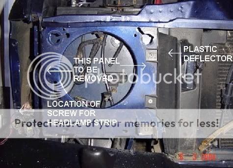
Once all the previous parts have been removed, its now time to start the not so nice part of the conversion as the metal panel that the old headlight was mounted on has to be removed. This is really the point of no return as once the panel is removed there is no going back.
There are different ways of approaching this, one being to fit a metal cutting disc to an angle grinder and just cut the panel out but this can leave a bit of a mess so I decided to remove the panel by drilling out all the spot welds.
You can use a special spot weld remover drill bit for this purpose but I did not have one to hand so just used an ordinary 7mm drill bit instead.
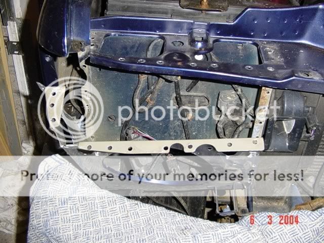
The following photos show the locations of the various spot welds to be removed, pay close attention to the folded seam under to top of the front wing, from the outside drill the visible spot welds out, then fold the outer metal lip upward, this gives access the the seam below and again the spot welds must be drilled to separate the remaining 2 panels.
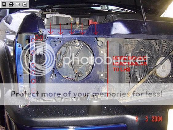
SPOT WELDS CIRCLED
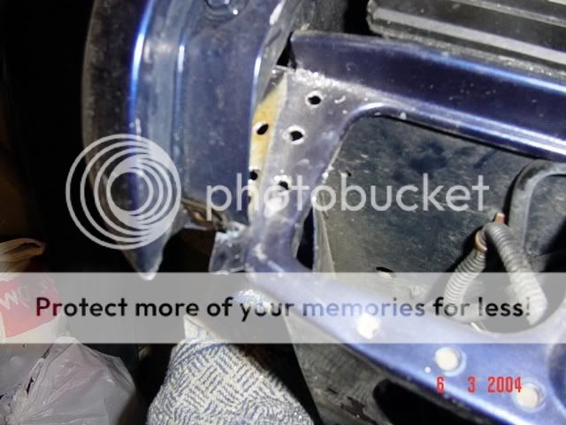
SPOT WELDS AT TRIPLE SEAM BELOW FRONT WING
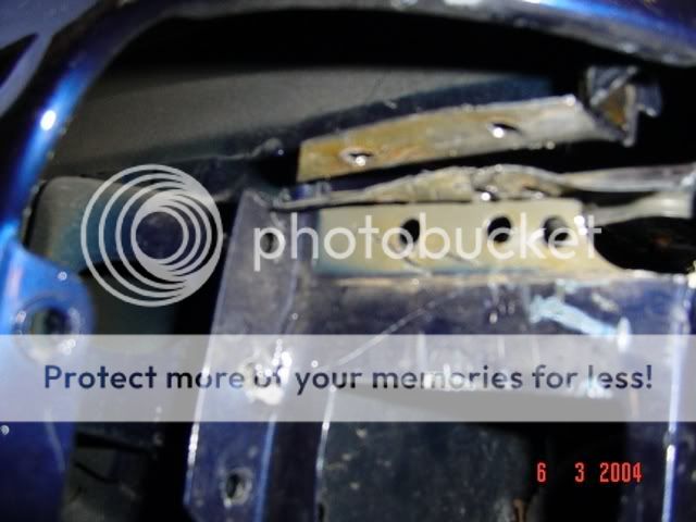
SPOT WELDS AT TRIPLE SEAM BELOW FRONT WING-SHOWING SEAMS FOLDED UPWARD - THIS SEAM MUST BE RE-WELDED OR SECURED
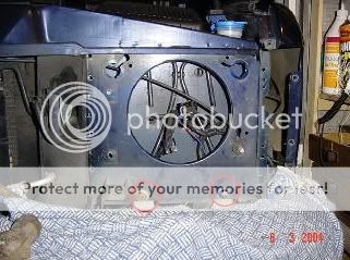
PANEL BEING REMOVED - YOU MAY HAVE TO PRISE SEAM APART WITH HAMMER/CHISEL
PANEL READY FOR REMOVAL - SEAMS DENOTED BY GREEN LINE REQUIRES TO BE RE-WELDED OR SECURED BY NUTS/BOLTS
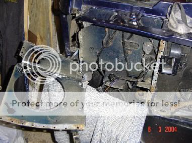
You cannot gain access to the base of the panel welds without removing the bumper - I did not want to do this so used some metal snips to cut along the bottom of the panel as shown in the photographs. When working on the passenger side of the car, you will find that the bottom of this panel acts as a mount for the screenwash tank so it has to remain in place anyway.
The photographs show the various locations of the welds and the panel being removed. Once the panel has been removed, the vertical seam nearest to the front wing (this also holds the front panel of the car to the inner wing) and lip at top of wing must be preferably re-welded together or at the very least bolted together. Welding is recommended but remember if using a MIG, disconnect the ECUs, alternator and battery to avoid damage. If the metal cutting disc is used, this would not be necessary.
A cut must also be made in the top of the front panel to accommodate the shape of the new headlight, again it is advisable to weld in a metal brace at the back of the light to retain panel strength.
Now is a good time to trial fit the light, some minor repositioning of cables/connectors at the back may be necessary. Treat all exposed metal with paint to avoid later rusting.
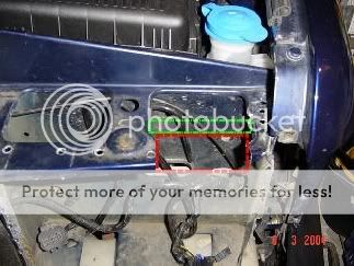
PASSENGER SIDE SHOWN WITH WASHER BOTTLE MOUNTS CIRCLED RED
PASSENGER SIDE SHOWN - CUTTING ALONG BASE WITH SNIPS
TOP PANEL REQUIRES TO BE CUT OUT AT BOTH DRIVER AND PASSENGER SIDE (SHOWN RED) TO ACCOMMODATE BODY OF HEADLIGHT - THIS TOP PANEL SLIDES INTO THE GROOVE IN THE TOP OF THE HEADLIGHT. SUGGEST METAL BRACE WELDED IN AT AREA SHOWN GREEN
Now its onto the wiring of the new lights. The 9 pin connector socket at the back of the new headlight unit is not suitable so must be removed. I decided to keep it in place as a seal against moisture ingress into the light unit.
Remove the socket by turning (you must overcome the small plastic stoppers) and the socket drops into the light unit. Use twine or similar to pull the wiring at the back of the socket and cut all the wires close to the socket back.
Now drill a hole in the side of the light unit and feed all the wires through this hole, place a rubber grommet around the hole and seal the wires in place with a suitable mastic. Finally turn the light unit upside down so that the socket drops down near the mounting hole, pull it through the hole and turn to lock it back in place.
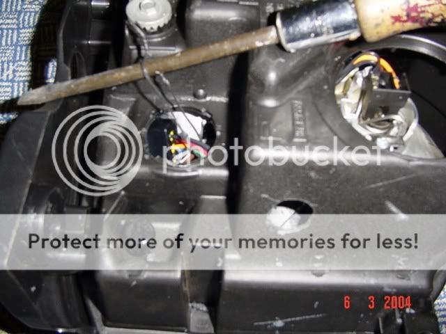
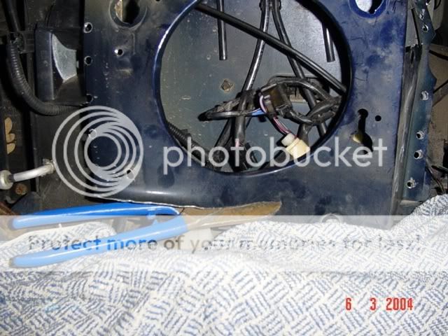
PHOTO SHOWING SOCKET WITH WIRES ATTACHED - TWINE USED TO PULL WIRES CLOSE TO THE HOLE
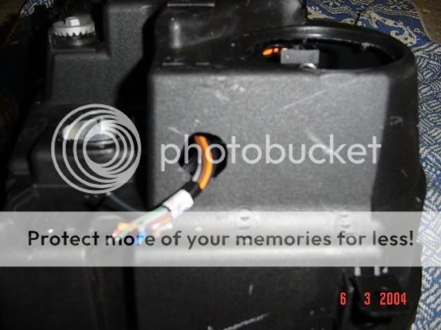
NEW HOLE DRILLED IN SIDE OF LIGHT UNIT AND 9 WIRES PUSHED THROUGH - INSTALL GROMMET TO HOLE
Each of the 9 wires that are sticking through the hole must be fitted with male type spade connectors - the white and green wires are for the headlamp levelling system (wiring of this not covered by this guide) so if these are not required, tape the ends up.
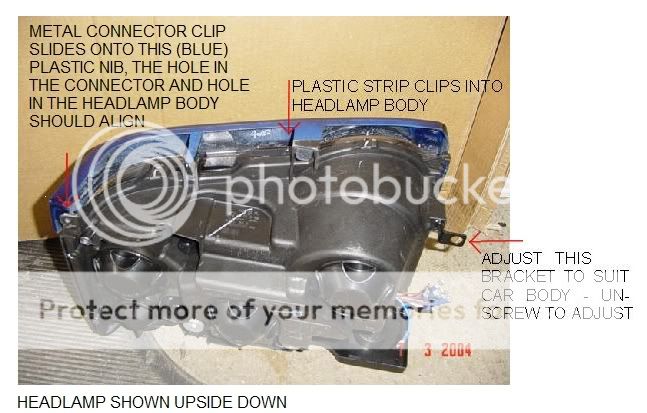
Now the headlamp bottom strip should be attached to the new headlight, the photo below shows how it clips into the base of the light unit, remember to install the metal connector clip onto the end of the strip so it can be secured against the wing.
Next stage is to prepare the wiring on the car to accept the new lights. The Discovery II old headlights have a double filament bulb and are wired in such a way that when you switch from dip beam to main beam, the dip beam is switched off (except when briefly flashing the lights). The new lights are different in 2 ways, firstly because they have separate light units for dip and main beam and secondly because when you switch from dip to main beam, the dip beam must stay on.
There is one other small difference which is that the old style indicator housing also contained a sidelight marker bulb - this is no longer required so the plug connector for these side markers should be taped up and stowed out of the way of the new lights.
First thing to do is, using one of the spot weld holes, prepare this to become an earthing point - the old headlight dip/main beam shared an earth cable but as the new lights are on together it is sensible to provide a separate main beam earth to prevent an overload on the wiring.
Use a small nut/bolt and washers to secure ring connectors to the car body through the spot weld hole - I used the same mount point as is required for the relay - see further on in text.
Locate the previously labeled headlamp connector plug, side light connector plug and indicator connector plug and cut off the plugs as close to the plug as you can - to provide maximum length of wires. The indicator earth wire is not required and can be taped up.
The following colouring of wiring is what was found on my car and in the light units I purchased, ensure you check your wiring with a test meter to ensure it is the same. Fit female spade connectors to the cut ends of the wiring loom of the car.
DRIVER SIDE WIRING
HEADLIGHT CONNECTOR PLUG
BLACK...............................................................CONNECT TO NEW LIGHT UNIT BROWN WIRE
BLUE/BLACK.........................................................CONNECT TO NEW LIGHT UNIT GREY WIRE
BLUE/ORANGE................................................CONNECT TO NEW LIGHT UNIT ORANGE WIRE
SIDE (PARKING) LIGHT CONNECTOR PLUG
BLACK.........................................................CONNECT TO NEW LIGHT UNIT THIN BLACK WIRE
RED/ORANGE..........................................................CONNECT TO NEW LIGHT UNIT RED WIRE
INDICATOR PLUG
GREEN/WHITE.......................................................CONNECT TO NEW LIGHT UNIT BLUE WIRE
NEW EARTH (GROUND) CABLE YOU HAVE INSTALLED
...................................................................CONNECT TO NEW LIGHT UNIT THICK BLACK WIRE
Next job is to install a relay which will allow the dipped beam lights to remain on, once you switch to main beam. This has only to be installed at one side as it controls both lights. Follow the wiring diagram below to connect the relay which is available from car accessory shops such as Halfords.
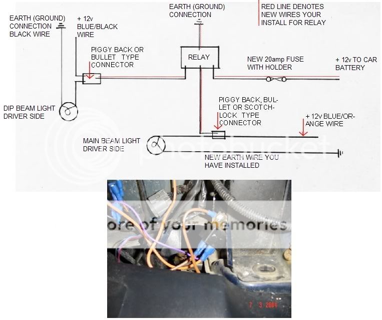
PHOTO SHOWING RELAY INSTALLED - WITH EARTH CONNECTOR ONTO SCREW MOUNT - (RELAY BRACKET IS RUSTY AS I HAD TO USE A SECOND HAND ONE - THE NEW ONE I BOUGHT WAS FAULTY! )- FOLLOW RELAY MANUFACTURERS INSTRUCTIONS FOR WIRING CONNECTIONS.
PASSENGER SIDE WIRING
HEADLIGHT CONNECTOR PLUG
BLACK...............................................................CONNECT TO NEW LIGHT UNIT BROWN WIRE
BLUE/LILAC...........................................................CONNECT TO NEW LIGHT UNIT GREY WIRE
BLUE/GREY.....................................................CONNECT TO NEW LIGHT UNIT ORANGE WIRE
SIDE (PARKING) LIGHT CONNECTOR PLUG
BLACK.........................................................CONNECT TO NEW LIGHT UNIT THIN BLACK WIRE
RED/BLACK..............................................................CONNECT TO NEW LIGHT UNIT RED WIRE
INDICATOR PLUG
GREEN/RED............................................................CONNECT TO NEW LIGHT UNIT BLUE WIRE
NEW EARTH (GROUND) CABLE YOU HAVE INSTALLED
...................................................................CONNECT TO NEW LIGHT UNIT THICK BLACK WIRE
I found that the length of the wiring was sufficient to just plug into the headlights, with the exception of the indicator wires - these had to be extended with a spade connector and some extra wiring.
Now you should be at as stage where all the wires from both the car wiring loom and from the new headlights are fitted with connectors and the relay installed. Temporarily fit the lights, connecting all the wires and check that they all work correctly and in the right sequence.
Now its best to tidy the installation, clipping both old and new wiring as required with cable clips etc - to ensure it dose not rub against the car body, that it is out of the way of the headlight body and that it cannot be seen from the small gap between the headlight strip and bumper.
Install each light in turn, first of all by fitting the self tapping screw that passes through the hole in the front wing and screws into the metal connector clip fitted to the plastic headlamp strip. When tight, ensure the light unit fits correctly into the recess in the front wing, then mark and drill pilot holes for the 2 top mounts and the lower inner mount (hidden by front grille)
I used self tapping bolts with large washers for these 3 mounts - the lower mounts behind the front grille have some adjustment available by unscrewing the bracket attached to the headlamp and sliding. However even with this adjustment, a small spacer (thick washer) was required.
Again, check the lights are working correctly.
Next fit the front grille. The now redundant mounting points on the grille (both sides) for the old headlamp strips need to be cut off with a hacksaw - see photo below. This shows the first cut I made but I found that I had to make a further cut (green line) to allow the grille to fit between the lights.
Locate the 2 bottom pegs of the grille into the holes in the car body and re-fit the 3 top securing screws.
Finally, park the car a few metres away from a flat surface (garage door) and using the 2 silver coloured bolts at the back of the headlight unit, adjust as required to ensure the lights have correct alignment - prior to starting the conversion its best to get an idea of position by using the beam pattern of the old lights as a template. This adjustment is not critical as you should get the alignement checked at a garage who has the correct equipment

Finished !
Rear lights to follow.
This guide has been compiled based on my own experiences in carrying out the Discovery light conversion. Whilst it has been carried out to the best of my knowledge, no liability can be accepted by me for loss, damage or injury caused by any errors in, or omissions from, the information given.
If you are in any doubt, you should consult a qualified motor mechanic or automotive electrician.
Prior to carrying out any electrical work, you should disconnect the car battery but remember that this will affect any radio security code and central locking - do not leave your keys in the car!
Before you start, its probably best to obtain all the likely parts and tools you will need. A suggested list is below. To install the front lights took me 2 days or about 11 hours in total. The back lights took 1 hour (easy once you have done the front!)
PARTS
Cable connectors - suggest 15AMP male & female spade type connectors perhaps 30 - 40 of each.
Insulating tape.
Selection of rubber grommets.
Piggy back style connectors for use with spade connectors.
Ring connectors.
Accessory relay. I bought one from a Motor Factor for £3.99 - 20 amp capacity.
Length of wire.
Landrover plastic finishing strips that fit below the headlights (Part numbers DHH 000120 LML & - DHH 000130 LML) These cost £16 (+vat) each from a Landrover dealer and have a moulded in curve to suit the new light. It is probably possible to modify the existing strips but fixing to the car could be a problem as the old strip locates into a cut-out in the grille, the new strip clips to the headlight.
Paint for headlamp strips - Landrover do a spray set comprising paint + lacquer for around £7.
Selection on nuts, bolts and screws.
TOOLS
In addition to the usual screwdrivers, pliers etc -
Wire stripper/crimper for spade connections.
Electrical test meter that can display voltage.
Selection of steel drill bits.
Spot weld remover drill bit (optional)
Metal cutting snips or other suitable cutting tool.
Welding equipment (optional)
1st stage is to remove the old headlights, indicators, finishing strip below headlight and front grille.
Follow the procedure in the owners handbook under bulb replacement in order to remove the headlight and indicator.
As you remove the various connectors, label them for easy reference.
To remove the finishing strip below the light, remove the crosshead screw - accessed from the wheelarch, the strip then pulls out from the slot in the front grille. The screw passes through a hole in the front wing lip, retained into a metal connector, clipped onto the finishing strip - retain this metal connector for use on the new finishing strip.
Remove the front grille by unscrewing the 3 screws along the top of the grille. Then prise out the plastic retainers and lift out the grille - it also has to plastic prongs located along its bottom edge that sit into holes in the car body.
Next, remove the 2 plastic deflectors (one either side of the grille) by drilling out the rivets - these deflectors can be discarded.
Now remove the headlamp electric leveling motors (if fitted) just turn the motor body until the prongs align with the cut outs in the metal and lift the motor out.
Once all the previous parts have been removed, its now time to start the not so nice part of the conversion as the metal panel that the old headlight was mounted on has to be removed. This is really the point of no return as once the panel is removed there is no going back.
There are different ways of approaching this, one being to fit a metal cutting disc to an angle grinder and just cut the panel out but this can leave a bit of a mess so I decided to remove the panel by drilling out all the spot welds.
You can use a special spot weld remover drill bit for this purpose but I did not have one to hand so just used an ordinary 7mm drill bit instead.
The following photos show the locations of the various spot welds to be removed, pay close attention to the folded seam under to top of the front wing, from the outside drill the visible spot welds out, then fold the outer metal lip upward, this gives access the the seam below and again the spot welds must be drilled to separate the remaining 2 panels.
SPOT WELDS CIRCLED
SPOT WELDS AT TRIPLE SEAM BELOW FRONT WING
SPOT WELDS AT TRIPLE SEAM BELOW FRONT WING-SHOWING SEAMS FOLDED UPWARD - THIS SEAM MUST BE RE-WELDED OR SECURED
PANEL BEING REMOVED - YOU MAY HAVE TO PRISE SEAM APART WITH HAMMER/CHISEL
PANEL READY FOR REMOVAL - SEAMS DENOTED BY GREEN LINE REQUIRES TO BE RE-WELDED OR SECURED BY NUTS/BOLTS
You cannot gain access to the base of the panel welds without removing the bumper - I did not want to do this so used some metal snips to cut along the bottom of the panel as shown in the photographs. When working on the passenger side of the car, you will find that the bottom of this panel acts as a mount for the screenwash tank so it has to remain in place anyway.
The photographs show the various locations of the welds and the panel being removed. Once the panel has been removed, the vertical seam nearest to the front wing (this also holds the front panel of the car to the inner wing) and lip at top of wing must be preferably re-welded together or at the very least bolted together. Welding is recommended but remember if using a MIG, disconnect the ECUs, alternator and battery to avoid damage. If the metal cutting disc is used, this would not be necessary.
A cut must also be made in the top of the front panel to accommodate the shape of the new headlight, again it is advisable to weld in a metal brace at the back of the light to retain panel strength.
Now is a good time to trial fit the light, some minor repositioning of cables/connectors at the back may be necessary. Treat all exposed metal with paint to avoid later rusting.
PASSENGER SIDE SHOWN WITH WASHER BOTTLE MOUNTS CIRCLED RED
PASSENGER SIDE SHOWN - CUTTING ALONG BASE WITH SNIPS
TOP PANEL REQUIRES TO BE CUT OUT AT BOTH DRIVER AND PASSENGER SIDE (SHOWN RED) TO ACCOMMODATE BODY OF HEADLIGHT - THIS TOP PANEL SLIDES INTO THE GROOVE IN THE TOP OF THE HEADLIGHT. SUGGEST METAL BRACE WELDED IN AT AREA SHOWN GREEN
Now its onto the wiring of the new lights. The 9 pin connector socket at the back of the new headlight unit is not suitable so must be removed. I decided to keep it in place as a seal against moisture ingress into the light unit.
Remove the socket by turning (you must overcome the small plastic stoppers) and the socket drops into the light unit. Use twine or similar to pull the wiring at the back of the socket and cut all the wires close to the socket back.
Now drill a hole in the side of the light unit and feed all the wires through this hole, place a rubber grommet around the hole and seal the wires in place with a suitable mastic. Finally turn the light unit upside down so that the socket drops down near the mounting hole, pull it through the hole and turn to lock it back in place.
PHOTO SHOWING SOCKET WITH WIRES ATTACHED - TWINE USED TO PULL WIRES CLOSE TO THE HOLE
NEW HOLE DRILLED IN SIDE OF LIGHT UNIT AND 9 WIRES PUSHED THROUGH - INSTALL GROMMET TO HOLE
Each of the 9 wires that are sticking through the hole must be fitted with male type spade connectors - the white and green wires are for the headlamp levelling system (wiring of this not covered by this guide) so if these are not required, tape the ends up.
Now the headlamp bottom strip should be attached to the new headlight, the photo below shows how it clips into the base of the light unit, remember to install the metal connector clip onto the end of the strip so it can be secured against the wing.
Next stage is to prepare the wiring on the car to accept the new lights. The Discovery II old headlights have a double filament bulb and are wired in such a way that when you switch from dip beam to main beam, the dip beam is switched off (except when briefly flashing the lights). The new lights are different in 2 ways, firstly because they have separate light units for dip and main beam and secondly because when you switch from dip to main beam, the dip beam must stay on.
There is one other small difference which is that the old style indicator housing also contained a sidelight marker bulb - this is no longer required so the plug connector for these side markers should be taped up and stowed out of the way of the new lights.
First thing to do is, using one of the spot weld holes, prepare this to become an earthing point - the old headlight dip/main beam shared an earth cable but as the new lights are on together it is sensible to provide a separate main beam earth to prevent an overload on the wiring.
Use a small nut/bolt and washers to secure ring connectors to the car body through the spot weld hole - I used the same mount point as is required for the relay - see further on in text.
Locate the previously labeled headlamp connector plug, side light connector plug and indicator connector plug and cut off the plugs as close to the plug as you can - to provide maximum length of wires. The indicator earth wire is not required and can be taped up.
The following colouring of wiring is what was found on my car and in the light units I purchased, ensure you check your wiring with a test meter to ensure it is the same. Fit female spade connectors to the cut ends of the wiring loom of the car.
DRIVER SIDE WIRING
HEADLIGHT CONNECTOR PLUG
BLACK...............................................................CONNECT TO NEW LIGHT UNIT BROWN WIRE
BLUE/BLACK.........................................................CONNECT TO NEW LIGHT UNIT GREY WIRE
BLUE/ORANGE................................................CONNECT TO NEW LIGHT UNIT ORANGE WIRE
SIDE (PARKING) LIGHT CONNECTOR PLUG
BLACK.........................................................CONNECT TO NEW LIGHT UNIT THIN BLACK WIRE
RED/ORANGE..........................................................CONNECT TO NEW LIGHT UNIT RED WIRE
INDICATOR PLUG
GREEN/WHITE.......................................................CONNECT TO NEW LIGHT UNIT BLUE WIRE
NEW EARTH (GROUND) CABLE YOU HAVE INSTALLED
...................................................................CONNECT TO NEW LIGHT UNIT THICK BLACK WIRE
Next job is to install a relay which will allow the dipped beam lights to remain on, once you switch to main beam. This has only to be installed at one side as it controls both lights. Follow the wiring diagram below to connect the relay which is available from car accessory shops such as Halfords.
PHOTO SHOWING RELAY INSTALLED - WITH EARTH CONNECTOR ONTO SCREW MOUNT - (RELAY BRACKET IS RUSTY AS I HAD TO USE A SECOND HAND ONE - THE NEW ONE I BOUGHT WAS FAULTY! )- FOLLOW RELAY MANUFACTURERS INSTRUCTIONS FOR WIRING CONNECTIONS.
PASSENGER SIDE WIRING
HEADLIGHT CONNECTOR PLUG
BLACK...............................................................CONNECT TO NEW LIGHT UNIT BROWN WIRE
BLUE/LILAC...........................................................CONNECT TO NEW LIGHT UNIT GREY WIRE
BLUE/GREY.....................................................CONNECT TO NEW LIGHT UNIT ORANGE WIRE
SIDE (PARKING) LIGHT CONNECTOR PLUG
BLACK.........................................................CONNECT TO NEW LIGHT UNIT THIN BLACK WIRE
RED/BLACK..............................................................CONNECT TO NEW LIGHT UNIT RED WIRE
INDICATOR PLUG
GREEN/RED............................................................CONNECT TO NEW LIGHT UNIT BLUE WIRE
NEW EARTH (GROUND) CABLE YOU HAVE INSTALLED
...................................................................CONNECT TO NEW LIGHT UNIT THICK BLACK WIRE
I found that the length of the wiring was sufficient to just plug into the headlights, with the exception of the indicator wires - these had to be extended with a spade connector and some extra wiring.
Now you should be at as stage where all the wires from both the car wiring loom and from the new headlights are fitted with connectors and the relay installed. Temporarily fit the lights, connecting all the wires and check that they all work correctly and in the right sequence.
Now its best to tidy the installation, clipping both old and new wiring as required with cable clips etc - to ensure it dose not rub against the car body, that it is out of the way of the headlight body and that it cannot be seen from the small gap between the headlight strip and bumper.
Install each light in turn, first of all by fitting the self tapping screw that passes through the hole in the front wing and screws into the metal connector clip fitted to the plastic headlamp strip. When tight, ensure the light unit fits correctly into the recess in the front wing, then mark and drill pilot holes for the 2 top mounts and the lower inner mount (hidden by front grille)
I used self tapping bolts with large washers for these 3 mounts - the lower mounts behind the front grille have some adjustment available by unscrewing the bracket attached to the headlamp and sliding. However even with this adjustment, a small spacer (thick washer) was required.
Again, check the lights are working correctly.
Next fit the front grille. The now redundant mounting points on the grille (both sides) for the old headlamp strips need to be cut off with a hacksaw - see photo below. This shows the first cut I made but I found that I had to make a further cut (green line) to allow the grille to fit between the lights.
Locate the 2 bottom pegs of the grille into the holes in the car body and re-fit the 3 top securing screws.
Finally, park the car a few metres away from a flat surface (garage door) and using the 2 silver coloured bolts at the back of the headlight unit, adjust as required to ensure the lights have correct alignment - prior to starting the conversion its best to get an idea of position by using the beam pattern of the old lights as a template. This adjustment is not critical as you should get the alignement checked at a garage who has the correct equipment
Finished !
Rear lights to follow.
 good write up
