Harmonic Balancer - where to get 4 bolt puller

This site contains affiliate links for which LandyZone may be compensated if you make a purchase.

Tirran

Well-Known Member
Posts
229
Location
South Lanarkshire
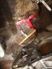
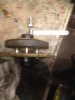
As expected my Harmonic Balancer is proving a complete b’stard to remove, does anyone know where I can get a 4 bolt puller? Everything I have seen so far is only 3 bolt.

I don’t want to damage it as a replacement is around £180!!

cheers

Bill
 
I drilled a piece of 1/2" plate for four securing bolts and drilled tapped centre hole for withdrawl bolt .
 

Attachments

  • IMG_1411.JPG
    IMG_1411.JPG
    281 KB · Views: 160
  • IMG_1412.JPG
    IMG_1412.JPG
    194.4 KB · Views: 174
Iirc the cheap tdi timing kits have a large round plate for holding the inj pump pulley in place whilst removing the pump, these also fit the crank damper.
Also good for pullng the cambelt gear off of the crank as well, but do need some extra bolts for that job.
 
It is, never thought about it as it is only the flywheel stop and FIP shaft I’ve used.
I hope it has the strength to pull off the Damper. Thanks.

I spent an age levering/hammering a 200 damper, then thought oh yeh that may work, the bloody thing just slid off with no issues!
 
I spent an age levering/hammering a 200 damper, then thought oh yeh that may work, the bloody thing just slid off with no issues!
Exactly what has happened tonight, used the timing kit items and off she came no problem, right tools and the jobs much easier.
The problem now is that the cam toothed wheel has a timing dot, the FIP wheel has two red dots of paint with no timing dot. My thinking is that the cam timing dot aligned with the arrow on the timing case , plus the engine at no1 tdc the locking pin should go into the FIP wheel. I know the crank rotates twice to move the cam and FIP into position. Then I can remove and replace the timing belt.

is my thinking sound?
 
Fip use one of the timing pins, you can see the hole through the pulley itself, and the hole is at the top.
The dots will just be a mech in the past doing it his way, or doubling up to make sure.
Basically crank slot at 12 oclock, insert timing pin into the flywheel housing and engage it into the flywheel slot, line up cam marks, pin in fip pulley, (pulley bolts loosened) fit belt, tension belt, tighetn fip pulley bolts, remove pinsm rotate engine by hand a couple of times, and make sure all the pins still fit, job done.
Thanks, just as I was intending, great thing about this forum is the ability to check your thinking.
 
93D1D06F-6899-45FE-AA50-59CB6FA53660.png


Picture worth a 100 words
Did mine with a locking pin in flywheel , FIP tool sliding fit in hole
Crank slot lined up with arrow
Cam wheel dimple lined up with casting

NB if you invert your engine it will look like pic above
 
Last edited:
Thanks that was at the end of a rebuild , it was really clean inside , it’s in my Series 3 now and running clean too no probs on any of the cogs getting them off
BD2686EA-A80C-40E8-82CD-1EB56B3BCE10.png
 
Back
Top