Tachometer

This site contains affiliate links for which LandyZone may be compensated if you make a purchase.

eprothe

Member
Posts
84
Location
Scotland
...yes, that old wheeze.

I'm trying to reverse-engineer a tachometer into my dashboard.
I've read in various places online that pin 19 of the ECU gives out some sort of engine-speed signal, but I'm having no luck detecting it.


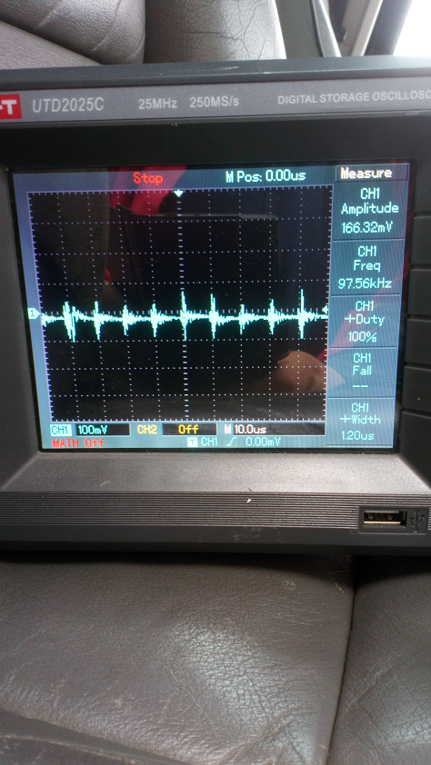
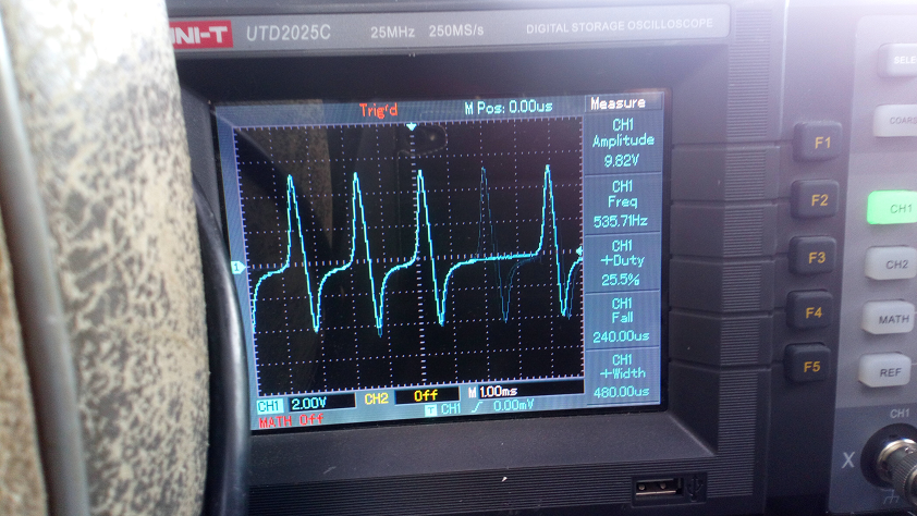
Here's the trace coming off pin 19, but I think it's just noise or some sort of RF rubbish coming out of the ECU.

All the wiring diagrams I've looked at suggest pin 19 of the ECU goes to the ABS system - my Defender doesn't have ABS, but the pin's obviously still available at the ECU end...it seems odd to me that the ABS would need to know the engine revs, though...

Can anybody tell me; is this pin-19 tacho thing actually true or is it just internet lies..?

Thanks :)
 
The Td5 ECU should have a engine speed output on pin 19 of the black plug(yellow/pink wire) which is used by the ABS ECU(on those fitted with it) for traction control management, it should be a 2 pulse/rev signal, are you sure you identified well pin 19 of the ECU black plug? ...if no joy try to work with the crank sensor's output across pins 13 - 36 of the red plug which is analog AC voltage signal
Defender rpm output.jpg
 
Last edited:
Hello,

thanks for the info.

I was pretty certain I'd identified pin 19 correctly, but now I'm not sure...

This post says that pin 19 is either yellow/pink or grey/white, which doesn't help. On my ECU, it's grey/white, which is the same as this post.

This diagram shows connector C0658 again, this time with a yellow/pink wire at pin 19 - I've been assuming that C0658 is always shown from the connector side (i.e. not the wire-side), so pin 1 is at the bottom of the connector, in the middle of the ECU - is that right?

Thanks for your help :)
 
The pinout view is from the connector side and to pin 19 should be YK for all td5s fitted with ABS, the WS wire i presume it's for non-ABS types but there can be misstakes though the pinout must be the same anyway but it's possible that for non-ABS vehicles the ADC which delivers the rpm signal to be disabled by default
 
That's a fair point - it seems likely to me that that's the case.
Do you know if pins 13/16 of the other (red) connector carry the same signal from the crank position sensor? Is it a 12V signal?

Thanks for your help :)
 
Right - that's handy to know - thanks for that.
I'm going to try picking up the signal from pins 13/36 and see what it looks like - I should be able to convert that into a signal to drive my tachometer.
Thanks very much for your help :)
 
Well, I cut into the wire to pin 13 and put a scope on it:

I noticed in the RAVE excerpt above that pin 13 is referred to as the positive signal - presumably, the a.c. output of the CKP sensor is centred about ground - the trace above is with the pin 13/36 screen as reference.

Anyway, that seemed promising - a few weird missing cycles (the TDC positions? Seems unlikely I'd see them at 500-ish rpm), but probably good enough to fool a tacho into thinking it's seeing the alternator "W" feed.

It all looks a bit mad, but it'll come right in the end...the box with a red light on it is a transistor switching circuit, to convert the roughly 6V max output of the CKP sensor into a signal at full supply voltage (i.e. however far off 14.4V the vehicle voltage is) otherwise, the tacho ignores it. The transistor must saturate almost as soon as the CKP signal goes positive, so presumably the signal going to the tacho is basically on/off rather than weirdly sinusoidal, as on the scope...I've not tried testing it.

The important bit is that the tacho basically works - hooray!

A better solution would be a comparator testing both pin 13 and 36, but I haven't got one handy and this seems to work. Ideally, the transistor circuit should be next to the ECU, so I don't have to run a long wire back to the dashboard - the wires going to pins 13/36 are screened against RFI and joining a long, unscreened wire to one of them can't be doing the signal any favours. If it starts causing problems (rough running, presumably), I'll re-organise everything.

Anyway - tacho needing a W feed into a Td5 without one? No problems :)

Thanks for your help/advice/links :)
 
Well....don't I feel like an idiot.

I thought this was working fine, but it's doing something weird I don't understand and I didn't notice it until I went for a proper drive :rolleyes:

The signal from the CKP sensor never goes beyond about 1500Hz, no matter how hard I rev the engine (obviously, this is a test I've done "within reason"). I also think that, in retrospect, my idling frequency of about 500Hz is actually a bit low - something like 800Hz (i.e. 800rpm) would be more what I'd expect.

So what's going on? Does the CKP sensor send out a single pulse per revolution or is it supposed to generate 36-5 pulses per rev, as each target segment on the flywheel passes it? it doesn't seem to be doing either, to be honest...

Thanks for any help :)
 
Thanks for the links - all interesting stuff.
I've played about with VRS sensors before on another vehicle, getting a speed signal from an ABS tone ring, so this doesn't seem that much different to me.
I'm not sure about the ECU taking the AC amplitude (or probably the rms) of the CKP sensor as its speed indicator - RAVE suggests that even a good CKP sensor has an approximate output (6~6.5V at 1k+ - mine is at about 9.8Vpk, so about 6.9Vrms) and I can't see how the ECU would calibrate against the sensor and flywheel target ring degrading over time - I think it must be getting the engine speed from the frequency.
I just don't understand how the signal frequency could be anything other than, at a minimum, the engine rpm - I could easily see how it could be a multiple, but not less than...
Weird :confused:
 
:rolleyes:
There I was explaining the problem to somebody and I suddenly realised why it isn't working...

Of course, 500Hz isn't 500rpm, is it? Engines don't work in rev's per second, they work in rev's per minute...quite how I managed to make that leap of stupidity is beyond me, but I'm back on the ball now...

So, 536Hz (as above), multiplied by 60 to get cycles per minute = 32160. Now, divide that by 36 target zones on the flywheel to give single rotations of the crankshaft per minute = 893.33rpm...which is much more like what it should be.

So, I know the engine's idling at about 500Hz = about 800rpm. The highest frequency I've seen stationary, revving the engine is about 1500Hz = about 2500rpm, so now it all seems to tie together.

Of course, this calls for a somewhat more involved solution to get the tacho working, but watch this space...
 
Right - here's "phase-1" of my solution:
td5_tacho_driver_01.JPG
...this is an Arduino with a 741 comparator built onto it - it takes in the signal from the two CKS wires, figures out the frequency by detecting the zero-crossover, multiplies that by 1.66 and outputs a signal to the tachometer.

td5_tacho_driver_02.JPG
...I put an LED display on it (mainly because I wanted to) to aid setting up etc.

td5_tacho_driver_03.JPG
...a bit tricky to see what's happening here, but the CKS sensor is coming in at 300Hz and the TACHO feed is going out at 1000Hz - the maths is wrong here, as, at 300Hz input, the flywheel should be spinning at 300 * (60/36) = 500rpm. For some reason I don't yet understand, the comparator isn't detecting the zero-crossing properly and is coming back at half the CKS frequency. Luckily, I thought a bit of "tuning" might be necessary, so I was able to double the output frequency, giving me 1000rpm.

td5_tacho_driver_04.JPG
...here it is in place, number-plate taped to the bottom of the ECU compartment.
td5_tacho_driver_05.JPG td5_tacho_driver_06.JPG
...and this is the proof of the pudding, as it were - the tacho now reads at the correct rpm...well, almost.

Right, so, phase-2... I realised, driving in this morning, that the tachometer is reading slightly low. I put all my Defender's numbers etc into this handy transmission calculator and it confirms that, at 60mph in fifth, I should be seeing about 2500rpm. In fact, I'm getting nigh-on exactly 2000rpm, so where's the missing 20% gone?

Well, the Td5 flywheel has 36 CKS zones that each returns a pulse to the ECU, but there are 5 missing, which allows the ECU to tell when each cylinder on the Td5 is at TDC. 31/36 = 0.86-ish, which isn't too far off the missing 20%. As I'm figuring out the rpm by counting pulses against time, not adding every fifth pulse to the count (because it's missing) makes the rpm comes out lower than it should.

The fix is pretty straight forward - multiply the input frequency by 1.2 before converting it to rpm...that's one line of code. The PITA bit is I have to unbolt the front seat (I've got Saab seats, not Defender seats) and get the Arduino back out of the ECU compartment to re-flash the code...twenty minutes with a spanner, fourteen seconds with a laptop and a USB cable...wish I'd thought of this beforehand, really.

Right, well, that's me, then - cheers for reading :)
 
Hi Eprothe

That's a super project and similar to one I'm planning. I'd be keen to get some info from you on your Arduino code and also the comparator circuit if that's something you'd be willing to share?

I'm planning to replace my 3 gauges with arduino/esp32 digital gauges and I'm learning as I go. I'm hoping to integrate fuel & engine temp into 1 gauges, clock/batt voltage/outside temp into another and then a 3rd for a not yet existing tacho. If you'd be willing to share your tacho info, it'd be greatly appreciated.

TIA, Greg
 
Back
Top