- Posts
- 83,310
- Location
- Embasinga stocæ
Hopefully you already know that to charge the leisure battery at the same time as the vehicles alternator is charging the starter battery, the simplest option is to connect a wire between the 2 batteries positive terminals, and to ensure that the leisure battery is separated from the starter battery when the engine is not running, you put a switch in that wire, and to do it automatically you can use a relay connected to an ignition switched source, a better way is to use the alternator to trigger the relay so it is only activated when the alternator is actually charging.

You've probably seen this picture before from the manual switch wiring, it's here with the relay drawn in to show the basics of the split charge systems, all split charge systems have a few things in common, they are.. the leisure battery needs it's negative terminal connected to the vans chassis earth.. the same as the starter battery is wired.. this is to ensure the charge going to the leisure battery gets back to the alternator who's earth is connected to the van's metalwork.. called chassis earth.
You also have a wire from both positive terminals that go to a convenient location where you'll be putting the switch of your choice.. in the case of a manual switch, then the wires would go to where ever you mount the switch.. usually near the dashboard, but the relay can go almost anywhere convenient, it can live near one of the batteries (usually the starter battery for convenience in connecting the relays trigger wire to the alternator or other engine trigger point) but it can go in the middle of the wire if you really wanted it to, just depends on the route you've taken to run the wires from the 2 batteries so they meet at a common location.
And the most important bit, there must be a fuse at the connection to each batteries positive terminal.
The actual wire size you choose to use is largely upto you, but bear in mind voltage drop if you have a long run from the starter battery to the leisure battery, aim to use wire that will allow at least 15 amps down the length of the wire you choose, use the voltage drop calculator (click here for it) from the wiring page to determine the size wire to use for the length of the run from battery to battery.
Remember to size the relay's current carrying capacity higher than the wire you use for safety, i.e. the standard Bosch automotive relay is rated at 30 amps, so 15 amp wire is fine for use with that, if you used 50 amp wire between the batteries, then a 70 amp relay is fine, just remember the fuses must be the weakest links in the system, so 50 amp wire, 70 amp relay, no more than 45 amp fuses in the holders as the wire is the next smallest thing, when choosing the wire size to use, there isn't much point to go above 50 amp wire between the batteries, it's just getting bulky then, and a 70 amp relay isn't that cheap either.. not to mention the large fuse holders you'll have to use, after the initial current has gone into the batteries (first 10 minutes) you'll probably only be putting in 5 amps to the leisure battery, remember, all this is assuming a 'normal' set up, where you have 1, 2 or even 3 leisure batteries making up your house battery bank, if you have 10 to give you a few thousand amp hours, then you shouldn't be reading this page anyway, as hopefully you know how to handle that current and wire it up appropriately.
That's the basics of the system, you just need to connect the wire between the batteries to the correct terminals on the relay, and connect the trigger wire and coil earth to the relay and your set.
Below are diagrams and some notes on how to connect the relay up depending on your chosen trigger source.
The ignition switched method:

This is how the relay is wired to have the relay close and connect the 2 batteries only when the ignition is turned on, this is the most basic way to wire it, with the drawbacks mentioned on the other page, terminal 30 is connected to the starter batteries positive terminal, terminal 87 on the relay is connected to the leisure batteries positive terminal, terminal 85 on the relay needs connecting to earth, in a similar way to how you connected the leisure battery's negative terminal to earth.. i.e. drill a hole for a self tapping screw (a small one this time) to go into in a convenient metal part of the van (check what's behind the metal before you drill, and use common sense.. i.e. don't drill into a single skinned panel that would mean the screw sticks out the other side. then clean away some paint from around the hole you just drilled, put the self tapping screw through the eyelet terminal you crimped onto the wire from the relay's terminal 85, and screw it into the hole, coat the screw and bare metal with something like Vaseline or paint to stop it rusting.
Then you have one terminal on the relay left to connect, this will be terminal 86, and is the one that when 12 volts is applied to it, triggers the relay, connecting the leisure battery to the starter battery, in this instance you will run a wire from the terminal on the relay to a convenient wire in the engine bay or dash board area of the vehicle (all depends where you have located the relay) that's live only when the ignition is turned on.
If your connection will be in the engine bay, and the engine is a diesel, then the fuel stop solenoid wire could be used to pick up power from, on a petrol engined van the positive connection to the ignition coil could be used, behind the dashboard the ignition switched wire to the stereo could be used and so on, but either way you must make sure the wire you choose to connect terminal 86 of the relay to is only live when the ignition is on, and at no other time.
To do this you really must use a voltage test light, click here if you've never used one before, test the cable you want to use is only live when the ignition is on, then try to find out what that wire runs on the van.. on older vehicles this isn't that important, but one a very modern vehicle with air bags, seat belt pre tensioner, ABS etc, you need to be careful exactly what you tap into, so if you can, try to connect into the supply to the stereo behind the dash if your uncertain, on most vans that had a stereo from new, the cable is the yellow one, but test it first.
The alternator trigger method:

With this method the wiring for the relay is the same as for the ignition switched method, i.e. terminal 85 connected to earth, terminal 30 to the starter battery, terminal 87 to the leisure battery, and this time terminal 86 is connected to the no charge warning light wire from the alternator, now obviously this method requires you gain access to the back of your vans alternator, be careful round there, as there is a usually unfused wire connected to the alternator that is live all the time, it's the charge wire and the other end is connected directly to the battery, on more modern vans there may be a fuse in the circuit, but it will be an expensive fuse rated at around 100 amps or more, last one I had to change cost £20 to replace!!
The charge wire is always the largest wire connected to the alternator, and it's usually bolted onto a stud on the back of the alternator (marked "D+" in most cases), this stud is usually not protected with an insulator, so if you poke around with something metal round there, and catch the stud in question while touching metalwork with the other end, sparks will fly, and trust me... they will be big sparks, if you can, disconnect one of the batteries terminals before poking around at the back of an alternator (starter battery obviously).. make sure you know your radio's code first tho.
If you know for certain which wire is the no charge wire, then connect the relay's trigger wire to that wire which ever way you see fit.. scotch lock, splice with a terminal, solder etc), and your done, if your unsure which wire to connect to, then read on:
As well as the big fat (usually red) main charge wire on the back of the alternator, there should be at least one more wire (there are one wire alternators out there, these as the name implies have only one wire, the big fat main charge wire, if you have one of these, then you can't trigger the relay this way I'm afraid)
Assuming you have a 'normal' alternator then, there will be at least one more wire, there could be more tho, but the wire your after should be connected to a terminal on the alternator marked "B+", this is the no charge warning light connection.. it's actually the connection that needs 12 volts from the battery on it to start the alternator charging when you start the engine.. (but now were getting more technical than we need to for this project) if there are other wires on your alternator, chances are one of them will be to a terminal marked "W", this is common on diesel engined vans, as it's a phase tap terminal, and it's used to run a rev counter.. even if your van doesn't have a rev counter, the W terminal could be used for a low oil pressure at high RPM's warning buzzer like VW's have.
On most alternators, the B+ connection is a spade terminal, but on some it's a smaller stud connection like the main charge wire.. Bosch alternators use this type of connection on the alternators fitted to certain VW's, some alternators have a plug arrangement for all the connections, Lucas alternators are sometimes like this, they also usually have 2 fat-ish wires for the main charge wire.. as the spade terminals can't carry as much current as the stud type connections can.. so they have to double up on the terminals and wires to make things safe)
You may well find a silver metal can on the back of the alternator, it'll have a wire coming out of it that will be connected to the main charge output stud along with the fat wire, this is a choke.. it's job is to absorb the electrical noise the alternator produces and prevent your radio picking it up, they're sometimes black square boxes too, leave that alone as it's there for a reason, on some alternators.. definitely the Bosch alternator fitted to Iveco TurboDaily vans, there's a second D+ connection, this one is a small spade terminal, and it's there specifically as a connection for a choke, don't confuse this connection as a handily placed B+ connection, it's connected to the main charge stud inside the alternator, so is live all the time the battery is connected.
There could be more connections on the back of the alternator, and unless your 120% sure you have found the correct terminal, you'll be wise to test it.. simple to do, disconnect the wire you think is the no charge warning lamp wire from the back of the alternator (if it's a Bosch alt with the stud for the no charge wire, you must disconnect the battery first, as the main charge stud is next to it, and if you short out the 2 studs while there's battery voltage on the main charge wire, you'll get some sparks again, and you could blow part of the alternators internals (the no charge warning light terminal may want 12 volts on it to start the alternator charging, but it expects no more than 0.15 of an amp to be fed to it.. this is taken care of via the no charge lamp's bulb letting no more current than that through it.. there's also usually a resistor across the bulbs terminals to limit the current to the required amount needed to start the alternator charging, and not damage it)
Once you've disconnected what you think is the no charge warning lamp's wire, re-connect the battery for a second and turn the ignition on, if the no charge warning lamp does not light anymore, then you've got the correct wire, if it does light, then the proper wire is obviously still connected to the alternator, and you'll have to try another wire and see if that's kills the no charge light when it's removed from the alternator, disconnect the battery again when you've found the correct wire to use, and connect the wire from the split charge relay's terminal 86 to that wire, and your all done.. use common sense and make a good connection, make it waterproof, and route the wire to the relay safely in the engine bay.. oh, don't forget to re-connect the battery now")
Now to answer a question I am always being asked...
How can the relay can work in the way we want it to if it's connected to the no charge light wire on the alternator, as to switch on the relay it needs 12 volts sending to terminal 86, and to switch the relay off it needs the voltage taking away from terminal 86, yet the alternator no charge light is on when the engine is not running.. and off when the engine has started and the alternator is producing a charge.. so wiring it up as i've just described the relay should be on when the alternator is not producing a charge, and it will switch off when the alternator is on-line and producing a charge.. basically the opposite of what we want to happen.... well, the simple answer is "just wire it up like shown, and it'll work", however some people don't believe me, so I have to explain how the no charge light on your dash board actually works.
Have a look at the picture below, this shows what happens when the engine is not running, but the ignition is turned on, you can see that there is no voltage on the wire from the no charge lamp to the alternator, so you must connect the relay's trigger wire after the lamp, preferably at the alternator, Once you've seen the picture and read the text, click on the picture, and you will see what happens to the circuit after the engine has been started, and hopefully you'll then see how the relay triggers when the light is not lit.

One last note, the alternator no charge light triggering method shown in these pages assumes you have a modern, internal regulator alternator, some older vehicles had an external regulator for the alternator, if you have one of these you'll most likely have a plug on the alternator with at least 3 wires in it, these will go to a box mounted somewhere in the engine bay, and more wires will go into and come out of that box, this makes things difficult as the no charge warning wire could be any one of these.. and some of those wires will appear to be the no charge warning light wire, but are for something else needed to make the external regulator work, I can only suggest you get hold of the workshop manual for your vehicle if you have an external regulator, and find out the wire colour or code for the no charge warning light wire, the main dealer may be able to help if you ask nicely
Final notes... possible problems when using the alternator switching method.
The alternator switching method seems to be the answer to all our problems, the relay is only operated when the alternator is actually producing a charge, so the batteries are only connected when they are going to receive a charge, but there are a couple of points you should be aware of when using this method.
Quenching diodes:
WTF is a quenching diode I hear you ask... firstly let me explain why you could need one,
It's all to do with the nature of the coil in the relay, remember it's used as an electromagnet, it's a coil of wire wrapped around an iron core, when you apply power to the coil, the resulting magnetic field pulls the relays contacts closed, the energy used to power the coil is stored in the coil, so when the relay's coil is de-energized by removing the power to the coil, the magnetic field collapses, this causes the relays coil to act like the coil on a petrol engines ignition system (with that a there are 2 coils inside each other, by applying voltage to one coil, then suddenly removing it, the collapsing magnetic field creates a very high voltage in the other coil, which creates the 40,000 volt spark that ignites the fuel)
Well, in the relays coil something similar happens, only not on such a grand scale, when the coils magnetic field collapses, it too creates a high voltage, but as there's only one coil, it creates in in the coil you were powering from the alternator, this causes an inductive kickback (also known as Back EMF) basically anything upto 200 volts can be sent back down the wire that was powering the relays coil.. and this is connected to the alternator, where it could be possible to cause some damage.
There is a way to prevent this inductive kickback from getting any further than the coil, and that's to use a diode across the coil like below.

A diode is an electrical one way valve, so voltage can only flow one way, and not the other, you'll have to go to an electronics shop (maplins) and get a small rectifier or switching diode.. (just ask for a 1N4001 diode it's a little black component with a solder lead coming out each end,
 with most electronic components, it has an anode and cathode lead, anode is for positive connection, and cathode negative connection, the anode on a diode is the one on the UNstriped end, i.e. voltage will flow through the diode from the unstriped end, and come out of the striped end, but not the other way round, for the use in the circuit above, you need to connect the diode so it's end with the stripe is to terminal 86, and the unstriped end goes to terminal 85, you MUST have the relay wired so that terminal 86 receives the 12 volts as shown, and terminal 85 is the earth connection.
With the diode in the circuit as above, when power is applied to trigger wire, the diode won't let and voltage pass through it's self, so the electricity goes through the coil, and the relays works as it should, when the power on the trigger wire is removed tho, the inductive kick back will flow through both terminals of the relay, and when it flows through terminal 85, the diode will let the voltage through, where it meets it's own voltage at terminal 86, and it dies out before it can get up the trigger wire to do any damage.
Some relays are sold with internal quenching diodes, also known as suppressed relays, these will have markings on them to show you must connect them up in a certain way.. i.e. if it says terminal 86 must be connected to positive (or +ve.. the electrical term for positive) then you must do that, like when you have fitted a quenching diode your self.. if you connect the +ve trigger wire to terminal 85, and the earth connection to terminal 86, while the diode is connected as shown you have a short circuit, in our application the alternator no charge light will never go out as your providing a false path to earth through the diode (the relays coil has resistance, so isn't a short circuit, hence why the no charge light does go out when it's triggered)
BUT, on that note we get to the final subject...
Relay current consumption and glowing lights:
As with all electrical loads, the relay will pull some current, the standard Bosch relay pulls about 150 milliamps, that's not a lot, but on a voltage sensitive circuit it can be.. and the alternator's no charge wire is voltage sensitive, you'll remember from above that the way the light works is to show any difference between the 2 voltages produced either side of the bulb, obviously at the extremes, when there's 12 volts on one side, and zero volts on the other, the light comes on at full brightness, BUT if there's 12 volts on one side, and say 10 volts on the other side because some voltage was being bled off.. like say through an old relay that's pulling more than it should, then the no charge light will glow.. maybe a little, maybe a lot.
When you get to wire up a fridge's 12 volt side in your vehicle, you use a second relay in parallel to the split charge one, this will then give you a 300 milliamp load on the no charge circuit, while for most alternators this is not a problem at all, some alternators don't like it, and the no charge light will glow slightly (don't be too quick to blame the relays for the glow instantly tho unless your 150% sure it never glowed before you fitted them, as a glowing no charge light is indicative of other things like poor earths and a bad battery, or even an overloaded charging system)
There is a little circuit you can make that will make the load the no charge light and alternator sees just 5 milliamps, you'll need to be able to solder to make this up, but it is very very easy to do, I might put that up next.
It is also worth considering an override single pole double throw switch (on-off-momentary) on the terminal 86 side of the relay - so that the batteries can be connected together electrically on the odd occasion when you need two batteries to start your vehicle (you never leave your lights on by mistake?), however a diode is required to ensure that you do not feed 12 volts on to the alternator.
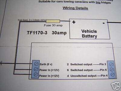
For those that are creating a split charge system for a caravan (or using that system for a landy) the relays usually have six connections, which should be wired as below..
1) Earth (0 Volts)
2) Power in (12 Volts)
3) Power in (12 volts) [2 and 3 can be used to feed two separate 15 Amp wires from the battery, so enabling lower current cable to be used]
4) Switched output a (to pin 2 on a 12S socket connector) [ Caravan battery/charger or spare]
5) Switched output b (to pin 6 on a 12S socket connector) [ Refridgerator]
6) Unswitched output (to pin 4 on a 12S socket connector) [Constant 12v {Interior Light & Charge}]
You've probably seen this picture before from the manual switch wiring, it's here with the relay drawn in to show the basics of the split charge systems, all split charge systems have a few things in common, they are.. the leisure battery needs it's negative terminal connected to the vans chassis earth.. the same as the starter battery is wired.. this is to ensure the charge going to the leisure battery gets back to the alternator who's earth is connected to the van's metalwork.. called chassis earth.
You also have a wire from both positive terminals that go to a convenient location where you'll be putting the switch of your choice.. in the case of a manual switch, then the wires would go to where ever you mount the switch.. usually near the dashboard, but the relay can go almost anywhere convenient, it can live near one of the batteries (usually the starter battery for convenience in connecting the relays trigger wire to the alternator or other engine trigger point) but it can go in the middle of the wire if you really wanted it to, just depends on the route you've taken to run the wires from the 2 batteries so they meet at a common location.
And the most important bit, there must be a fuse at the connection to each batteries positive terminal.
The actual wire size you choose to use is largely upto you, but bear in mind voltage drop if you have a long run from the starter battery to the leisure battery, aim to use wire that will allow at least 15 amps down the length of the wire you choose, use the voltage drop calculator (click here for it) from the wiring page to determine the size wire to use for the length of the run from battery to battery.
Remember to size the relay's current carrying capacity higher than the wire you use for safety, i.e. the standard Bosch automotive relay is rated at 30 amps, so 15 amp wire is fine for use with that, if you used 50 amp wire between the batteries, then a 70 amp relay is fine, just remember the fuses must be the weakest links in the system, so 50 amp wire, 70 amp relay, no more than 45 amp fuses in the holders as the wire is the next smallest thing, when choosing the wire size to use, there isn't much point to go above 50 amp wire between the batteries, it's just getting bulky then, and a 70 amp relay isn't that cheap either.. not to mention the large fuse holders you'll have to use, after the initial current has gone into the batteries (first 10 minutes) you'll probably only be putting in 5 amps to the leisure battery, remember, all this is assuming a 'normal' set up, where you have 1, 2 or even 3 leisure batteries making up your house battery bank, if you have 10 to give you a few thousand amp hours, then you shouldn't be reading this page anyway, as hopefully you know how to handle that current and wire it up appropriately.
That's the basics of the system, you just need to connect the wire between the batteries to the correct terminals on the relay, and connect the trigger wire and coil earth to the relay and your set.
Below are diagrams and some notes on how to connect the relay up depending on your chosen trigger source.
The ignition switched method:
This is how the relay is wired to have the relay close and connect the 2 batteries only when the ignition is turned on, this is the most basic way to wire it, with the drawbacks mentioned on the other page, terminal 30 is connected to the starter batteries positive terminal, terminal 87 on the relay is connected to the leisure batteries positive terminal, terminal 85 on the relay needs connecting to earth, in a similar way to how you connected the leisure battery's negative terminal to earth.. i.e. drill a hole for a self tapping screw (a small one this time) to go into in a convenient metal part of the van (check what's behind the metal before you drill, and use common sense.. i.e. don't drill into a single skinned panel that would mean the screw sticks out the other side. then clean away some paint from around the hole you just drilled, put the self tapping screw through the eyelet terminal you crimped onto the wire from the relay's terminal 85, and screw it into the hole, coat the screw and bare metal with something like Vaseline or paint to stop it rusting.
Then you have one terminal on the relay left to connect, this will be terminal 86, and is the one that when 12 volts is applied to it, triggers the relay, connecting the leisure battery to the starter battery, in this instance you will run a wire from the terminal on the relay to a convenient wire in the engine bay or dash board area of the vehicle (all depends where you have located the relay) that's live only when the ignition is turned on.
If your connection will be in the engine bay, and the engine is a diesel, then the fuel stop solenoid wire could be used to pick up power from, on a petrol engined van the positive connection to the ignition coil could be used, behind the dashboard the ignition switched wire to the stereo could be used and so on, but either way you must make sure the wire you choose to connect terminal 86 of the relay to is only live when the ignition is on, and at no other time.
To do this you really must use a voltage test light, click here if you've never used one before, test the cable you want to use is only live when the ignition is on, then try to find out what that wire runs on the van.. on older vehicles this isn't that important, but one a very modern vehicle with air bags, seat belt pre tensioner, ABS etc, you need to be careful exactly what you tap into, so if you can, try to connect into the supply to the stereo behind the dash if your uncertain, on most vans that had a stereo from new, the cable is the yellow one, but test it first.
The alternator trigger method:
With this method the wiring for the relay is the same as for the ignition switched method, i.e. terminal 85 connected to earth, terminal 30 to the starter battery, terminal 87 to the leisure battery, and this time terminal 86 is connected to the no charge warning light wire from the alternator, now obviously this method requires you gain access to the back of your vans alternator, be careful round there, as there is a usually unfused wire connected to the alternator that is live all the time, it's the charge wire and the other end is connected directly to the battery, on more modern vans there may be a fuse in the circuit, but it will be an expensive fuse rated at around 100 amps or more, last one I had to change cost £20 to replace!!
The charge wire is always the largest wire connected to the alternator, and it's usually bolted onto a stud on the back of the alternator (marked "D+" in most cases), this stud is usually not protected with an insulator, so if you poke around with something metal round there, and catch the stud in question while touching metalwork with the other end, sparks will fly, and trust me... they will be big sparks, if you can, disconnect one of the batteries terminals before poking around at the back of an alternator (starter battery obviously).. make sure you know your radio's code first tho.
If you know for certain which wire is the no charge wire, then connect the relay's trigger wire to that wire which ever way you see fit.. scotch lock, splice with a terminal, solder etc), and your done, if your unsure which wire to connect to, then read on:
As well as the big fat (usually red) main charge wire on the back of the alternator, there should be at least one more wire (there are one wire alternators out there, these as the name implies have only one wire, the big fat main charge wire, if you have one of these, then you can't trigger the relay this way I'm afraid)
Assuming you have a 'normal' alternator then, there will be at least one more wire, there could be more tho, but the wire your after should be connected to a terminal on the alternator marked "B+", this is the no charge warning light connection.. it's actually the connection that needs 12 volts from the battery on it to start the alternator charging when you start the engine.. (but now were getting more technical than we need to for this project) if there are other wires on your alternator, chances are one of them will be to a terminal marked "W", this is common on diesel engined vans, as it's a phase tap terminal, and it's used to run a rev counter.. even if your van doesn't have a rev counter, the W terminal could be used for a low oil pressure at high RPM's warning buzzer like VW's have.
On most alternators, the B+ connection is a spade terminal, but on some it's a smaller stud connection like the main charge wire.. Bosch alternators use this type of connection on the alternators fitted to certain VW's, some alternators have a plug arrangement for all the connections, Lucas alternators are sometimes like this, they also usually have 2 fat-ish wires for the main charge wire.. as the spade terminals can't carry as much current as the stud type connections can.. so they have to double up on the terminals and wires to make things safe)
You may well find a silver metal can on the back of the alternator, it'll have a wire coming out of it that will be connected to the main charge output stud along with the fat wire, this is a choke.. it's job is to absorb the electrical noise the alternator produces and prevent your radio picking it up, they're sometimes black square boxes too, leave that alone as it's there for a reason, on some alternators.. definitely the Bosch alternator fitted to Iveco TurboDaily vans, there's a second D+ connection, this one is a small spade terminal, and it's there specifically as a connection for a choke, don't confuse this connection as a handily placed B+ connection, it's connected to the main charge stud inside the alternator, so is live all the time the battery is connected.
There could be more connections on the back of the alternator, and unless your 120% sure you have found the correct terminal, you'll be wise to test it.. simple to do, disconnect the wire you think is the no charge warning lamp wire from the back of the alternator (if it's a Bosch alt with the stud for the no charge wire, you must disconnect the battery first, as the main charge stud is next to it, and if you short out the 2 studs while there's battery voltage on the main charge wire, you'll get some sparks again, and you could blow part of the alternators internals (the no charge warning light terminal may want 12 volts on it to start the alternator charging, but it expects no more than 0.15 of an amp to be fed to it.. this is taken care of via the no charge lamp's bulb letting no more current than that through it.. there's also usually a resistor across the bulbs terminals to limit the current to the required amount needed to start the alternator charging, and not damage it)
Once you've disconnected what you think is the no charge warning lamp's wire, re-connect the battery for a second and turn the ignition on, if the no charge warning lamp does not light anymore, then you've got the correct wire, if it does light, then the proper wire is obviously still connected to the alternator, and you'll have to try another wire and see if that's kills the no charge light when it's removed from the alternator, disconnect the battery again when you've found the correct wire to use, and connect the wire from the split charge relay's terminal 86 to that wire, and your all done.. use common sense and make a good connection, make it waterproof, and route the wire to the relay safely in the engine bay.. oh, don't forget to re-connect the battery now
Now to answer a question I am always being asked...
How can the relay can work in the way we want it to if it's connected to the no charge light wire on the alternator, as to switch on the relay it needs 12 volts sending to terminal 86, and to switch the relay off it needs the voltage taking away from terminal 86, yet the alternator no charge light is on when the engine is not running.. and off when the engine has started and the alternator is producing a charge.. so wiring it up as i've just described the relay should be on when the alternator is not producing a charge, and it will switch off when the alternator is on-line and producing a charge.. basically the opposite of what we want to happen.... well, the simple answer is "just wire it up like shown, and it'll work", however some people don't believe me, so I have to explain how the no charge light on your dash board actually works.
Have a look at the picture below, this shows what happens when the engine is not running, but the ignition is turned on, you can see that there is no voltage on the wire from the no charge lamp to the alternator, so you must connect the relay's trigger wire after the lamp, preferably at the alternator, Once you've seen the picture and read the text, click on the picture, and you will see what happens to the circuit after the engine has been started, and hopefully you'll then see how the relay triggers when the light is not lit.
One last note, the alternator no charge light triggering method shown in these pages assumes you have a modern, internal regulator alternator, some older vehicles had an external regulator for the alternator, if you have one of these you'll most likely have a plug on the alternator with at least 3 wires in it, these will go to a box mounted somewhere in the engine bay, and more wires will go into and come out of that box, this makes things difficult as the no charge warning wire could be any one of these.. and some of those wires will appear to be the no charge warning light wire, but are for something else needed to make the external regulator work, I can only suggest you get hold of the workshop manual for your vehicle if you have an external regulator, and find out the wire colour or code for the no charge warning light wire, the main dealer may be able to help if you ask nicely
Final notes... possible problems when using the alternator switching method.
The alternator switching method seems to be the answer to all our problems, the relay is only operated when the alternator is actually producing a charge, so the batteries are only connected when they are going to receive a charge, but there are a couple of points you should be aware of when using this method.
Quenching diodes:
WTF is a quenching diode I hear you ask... firstly let me explain why you could need one,
It's all to do with the nature of the coil in the relay, remember it's used as an electromagnet, it's a coil of wire wrapped around an iron core, when you apply power to the coil, the resulting magnetic field pulls the relays contacts closed, the energy used to power the coil is stored in the coil, so when the relay's coil is de-energized by removing the power to the coil, the magnetic field collapses, this causes the relays coil to act like the coil on a petrol engines ignition system (with that a there are 2 coils inside each other, by applying voltage to one coil, then suddenly removing it, the collapsing magnetic field creates a very high voltage in the other coil, which creates the 40,000 volt spark that ignites the fuel)
Well, in the relays coil something similar happens, only not on such a grand scale, when the coils magnetic field collapses, it too creates a high voltage, but as there's only one coil, it creates in in the coil you were powering from the alternator, this causes an inductive kickback (also known as Back EMF) basically anything upto 200 volts can be sent back down the wire that was powering the relays coil.. and this is connected to the alternator, where it could be possible to cause some damage.
There is a way to prevent this inductive kickback from getting any further than the coil, and that's to use a diode across the coil like below.
A diode is an electrical one way valve, so voltage can only flow one way, and not the other, you'll have to go to an electronics shop (maplins) and get a small rectifier or switching diode.. (just ask for a 1N4001 diode
it's a little black component with a solder lead coming out each end,
With the diode in the circuit as above, when power is applied to trigger wire, the diode won't let and voltage pass through it's self, so the electricity goes through the coil, and the relays works as it should, when the power on the trigger wire is removed tho, the inductive kick back will flow through both terminals of the relay, and when it flows through terminal 85, the diode will let the voltage through, where it meets it's own voltage at terminal 86, and it dies out before it can get up the trigger wire to do any damage.
Some relays are sold with internal quenching diodes, also known as suppressed relays, these will have markings on them to show you must connect them up in a certain way.. i.e. if it says terminal 86 must be connected to positive (or +ve.. the electrical term for positive) then you must do that, like when you have fitted a quenching diode your self.. if you connect the +ve trigger wire to terminal 85, and the earth connection to terminal 86, while the diode is connected as shown you have a short circuit, in our application the alternator no charge light will never go out as your providing a false path to earth through the diode (the relays coil has resistance, so isn't a short circuit, hence why the no charge light does go out when it's triggered)
BUT, on that note we get to the final subject...
Relay current consumption and glowing lights:
As with all electrical loads, the relay will pull some current, the standard Bosch relay pulls about 150 milliamps, that's not a lot, but on a voltage sensitive circuit it can be.. and the alternator's no charge wire is voltage sensitive, you'll remember from above that the way the light works is to show any difference between the 2 voltages produced either side of the bulb, obviously at the extremes, when there's 12 volts on one side, and zero volts on the other, the light comes on at full brightness, BUT if there's 12 volts on one side, and say 10 volts on the other side because some voltage was being bled off.. like say through an old relay that's pulling more than it should, then the no charge light will glow.. maybe a little, maybe a lot.
When you get to wire up a fridge's 12 volt side in your vehicle, you use a second relay in parallel to the split charge one, this will then give you a 300 milliamp load on the no charge circuit, while for most alternators this is not a problem at all, some alternators don't like it, and the no charge light will glow slightly (don't be too quick to blame the relays for the glow instantly tho unless your 150% sure it never glowed before you fitted them, as a glowing no charge light is indicative of other things like poor earths and a bad battery, or even an overloaded charging system)
There is a little circuit you can make that will make the load the no charge light and alternator sees just 5 milliamps, you'll need to be able to solder to make this up, but it is very very easy to do, I might put that up next.
It is also worth considering an override single pole double throw switch (on-off-momentary) on the terminal 86 side of the relay - so that the batteries can be connected together electrically on the odd occasion when you need two batteries to start your vehicle (you never leave your lights on by mistake?), however a diode is required to ensure that you do not feed 12 volts on to the alternator.
For those that are creating a split charge system for a caravan (or using that system for a landy) the relays usually have six connections, which should be wired as below..
1) Earth (0 Volts)
2) Power in (12 Volts)
3) Power in (12 volts) [2 and 3 can be used to feed two separate 15 Amp wires from the battery, so enabling lower current cable to be used]
4) Switched output a (to pin 2 on a 12S socket connector) [ Caravan battery/charger or spare]
5) Switched output b (to pin 6 on a 12S socket connector) [ Refridgerator]
6) Unswitched output (to pin 4 on a 12S socket connector) [Constant 12v {Interior Light & Charge}]