- Posts
- 9,105
- Location
- Roaming the UK on assignments
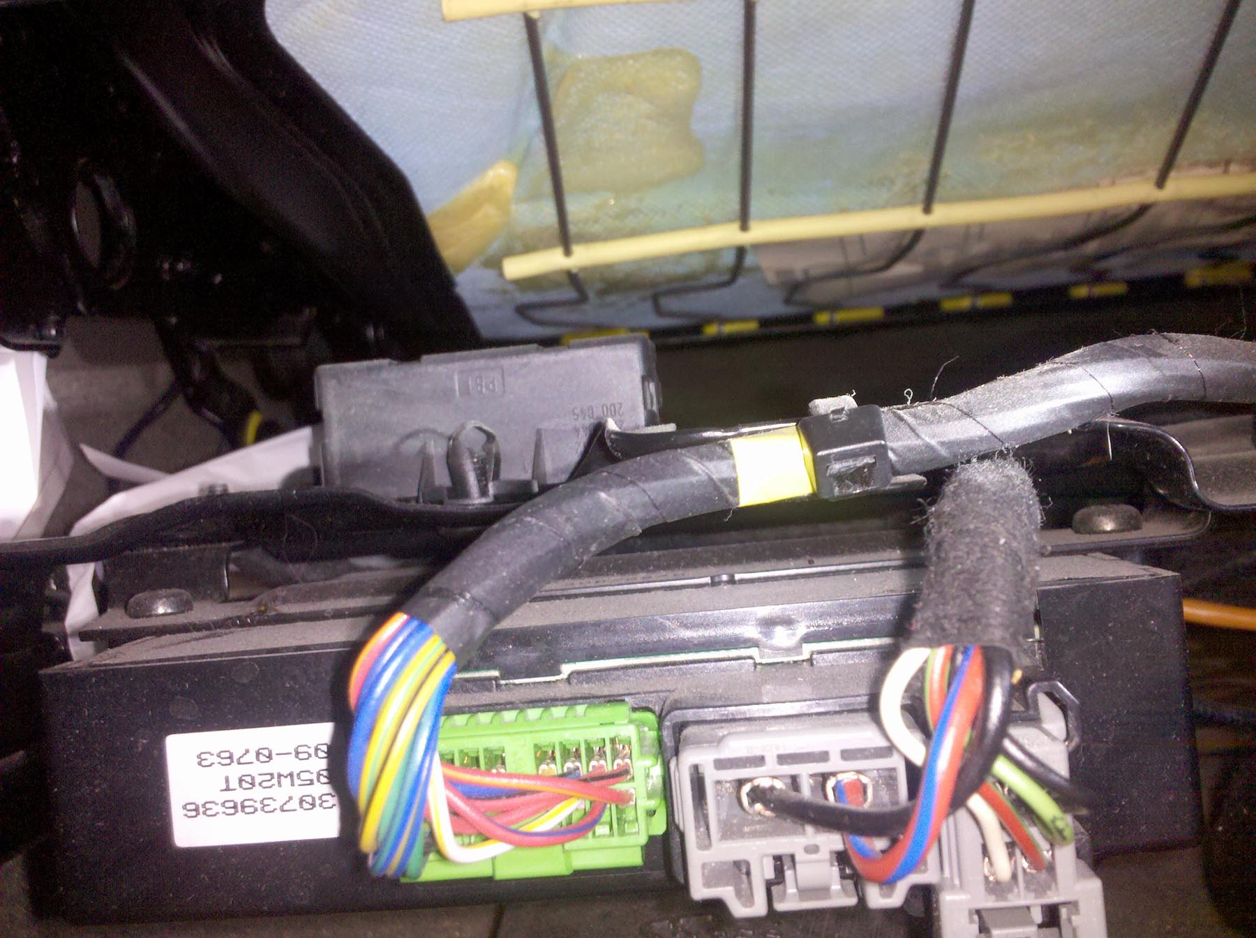
I hope they are, the Bosch one on the seat is a standard polarity one I think. Everything plugged into jct boxes and all sorts of ****e but I’m hoping that was just to accommodate the in cab controls and being able to do things at the same time
Need to try and find a wiring diagram for them.