Disco 2 Rear storage box fixings question...

This site contains affiliate links for which LandyZone may be compensated if you make a purchase.
I thought this posted successfully yesterday - obviously it didn't, so let's try again...

You lot are going to love this :oops::rolleyes:

There is a funny side to everything.

Seriously, there is.

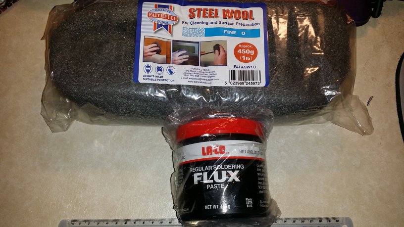
The other day, I checked my stores, and found no solder flux paste or fine steel wool.

I haven't bought any for ages, and this, at the end of a long day, meant a quick visit to Amazon or similar to get it overnight. I went to Amazon, chose prime delivery, 'grabbed' the first two things that looked right, hit 'buy', and thought nothing more about it, until they arrived not twenty minute ago.

JEEEEEeeeeeyyyyaaaaaayzus on a bike, when the hell will I learn to read the quantities I'm buying?! :mad::confused:

That's ONE POUND (450 grams) of steel wire wool (fine grade) and a shade over a pound of Soldering flux paste (475 grams)!o_Oo_Oo_O

There is only one thing I can say to this (bar the comment that I'm likely not to ever need to order any of this stuff again in my next two lifetimes):

D'OH! :D

D-OH.jpg
 
First and foremost, I'm VERY glad I had the foresight to invest in a full kit of these things a while back. They were utterly invaluable in saving me time and swear words today!
car-trim-kit.jpg


This is the where I decided to bring the cable out into the open air. It's between the legs of the spare wheel carrier, just alongside the window wash pipe exit. The antenna cable then drifts over the offside (right) leg of the spare wheel carrier, to the boot lip mount fitted to the hinge-side of the tailgate door, above the hinges.
rear-cable-entry.jpg


This is the mounting, with the antenna fitted.
rear-2.jpg

rear-1.jpg


The nearside (left) storage bin, looking down. The tightly wrapped cable top left of the picture is the programming lead (it's a spare, I have two), there for convenience. The radio was deliberately mounted top-down, to allow me to easily plug in the programming cable in situ, rather than faffing around removing the radio every time I want to program it. Laptop PCs were invented to be portable after all, so when I want to add/change radio settings, out comes the laptop, plug it into the radio, and a short while later, with little hassle at all, Bob's yer uncle :)
bin-mount-and-cables.jpg


The two cables from the radio to the front of the Disco actually DID go into the headlining trim (this is where the trim kit came into it's own), and out again at the bottom left (nearside) of the windscreen. It's secured there by a cable tie and a self-adhesive mounting.
into-the-trim.jpg


Finally, the head unit, speaker, and other gubbins on the dash...

The head unit is fixed in place in it's mount by a pair of small 'L' brackets which are screwed in place. The external speaker is fixed in place by a pair of double-sided adhesive pads (I appear to have lost the U bracket for the damn thing, mutter mutter). In this photo, the cables haven't been tidied up, yet. I may change the mounting method before long; I'm not quite happy with it just yet; I'm considering a goose-neck suction mount attached to the windscreen, but I'm going to give the current setup a go, and see how it works. The mount to the right of the speaker is my phone mount.
dash-fit.jpg


Anyhow, after all the sagas and mishaps along the way, it's now done :)

Hope the above helps someone in the future :)

looking good mate , surprising how long some things take

but always worth it in the end
 
looking good mate , surprising how long some things take

Thanks, and no kidding! Still not happy with the VSWR. It's excellent on 2m (practically 1:1, the needles on the meter hardly move), but for everything else it's a bit higher, esp on 6m and 10m.

I'm pretty sure the higher than desired VSWR is down to the grounding of the cable. When things calm down over here a bit, and I get some time to do it, I'm going to replace the utter rubbish RG-58/U stuff, which has a truly miserly amount of really crap screen (took three attempts to get a PL-259 on the end of it due to the braid breaking all the time, ffs :mad:), with some better coax. I already have the coax (some decent RG-58/U Coax made by Messi & Paoloni, sourced from ML&S) and a spare PL-259 or two lying around, all I have to do then is thread it through the body of the wagon (OVER the back door this time) and terminate it with connectors. The problem connector is going to be the one at the antenna mount; it's a right-angle crimp SO-239 job with a long neck up to the antenna, through the boot lip mounting, onto which it's bolted (Diamond K-405 mount. The mount is bloody marvellous, it's just the cable they used which is utter pants :().

but always worth it in the end

Oh, yes, without a doubt :D

Would the speaker fit the other side of the binnacle (it between it and the A pillar?) - might be a bit more discreet there? Nice job though.

It's a little wide for there, or that's where it would have gone ;) Good thinking though, and thanks :D
 
Thanks, and no kidding! Still not happy with the VSWR. It's excellent on 2m (practically 1:1, the needles on the meter hardly move), but for everything else it's a bit higher, esp on 6m and 10m.

I'm pretty sure the higher than desired VSWR is down to the grounding of the cable. When things calm down over here a bit, and I get some time to do it, I'm going to replace the utter rubbish RG-58/U stuff, which has a truly miserly amount of really crap screen (took three attempts to get a PL-259 on the end of it due to the braid breaking all the time, ffs :mad:), with some better coax. I already have the coax (some decent RG-58/U Coax made by Messi & Paoloni, sourced from ML&S) and a spare PL-259 or two lying around, all I have to do then is thread it through the body of the wagon (OVER the back door this time) and terminate it with connectors. The problem connector is going to be the one at the antenna mount; it's a right-angle crimp SO-239 job with a long neck up to the antenna, through the boot lip mounting, onto which it's bolted (Diamond K-405 mount. The mount is bloody marvellous, it's just the cable they used which is utter pants :().


Oh, yes, without a doubt :D


It's a little wide for there, or that's where it would have gone ;) Good thinking though, and thanks :D

going to do mine at some stage

i've got a TTi 900 cb

found a place to hide the cb in the glovebox out of the way, only thing though i would have to get an extension lead for the mic

will be removing the headlining so thinking of putting an aerial in then , a pre drilled hole where the gps normally goes

or on the roof rack mounts

these are some i've seen

IMG_0944.JPG
IMG_0960.JPG
IMG_1735.JPG


IMG_0957.JPG
 
Yeah, there are a few places you can stick a radio in a disco, no matter what model you have. If you do go for that gps hole, make sure you seal it effectively, discos really don't like leaks! :eek:
 
Yeah, there are a few places you can stick a radio in a disco, no matter what model you have. If you do go for that gps hole, make sure you seal it effectively, discos really don't like leaks! :eek:

got some really good glazing silicone if i go the roof option , lol

seen some plates u can get, then sandwich some rubber in between

pic is of the plate

IMG_0961.JPG
 
Aerials can cause untold headscratching and tearing out of hair (for those who might still have some).
SWR or more correctly, Voltage Standing Wave Ratio is the ratio between the forward voltage on a transmission line and the reverse or return voltage "reflected" back off the end of the transmission line, but is often used to indicate how well a load , in this case an aerial is tuned. A ratio of 1:1 indicates that all the power transmitted into the load is absorbed and none is reflected back. In reality, if I ever saw a test result of 1:1 I would suspect an aerial fault, nothing is ever that good. 1.1:1 or 1.2:1 is probably the best you can expect in the real world.
There are essentially two components which constitute a tuned load or circuit, inductance and capacitance. Those who have any knowledge of radio should know "One over two pi, root LC"
99971532401f7f6241b673c877f346889bce39a7.png

The length of the radiating element generally changes the inductance more than the capacitance and therefore the tuning. However most commecially built aerials are designed to work against a flat groundplane and they are tuned with such a groundplane taken into account.
As soon as the user starts bending that groundplane upwards and hence parallel to the radiating element the optimum tuning on a flat groundplane starts to change and also the capacitive effects between the radiating element and the groundplane change quite dramatically further altering the tuned frequency possibly to a point outside the ability to tune out the error.
Not only will such bending of the groundplane create errors in the tuning, but will also alter the horizontal radiation pattern from the aerial. On the flat test groundplane the horizontal radiation pattern from a vertical radiating element should be near enough circular, with a bent groundplane, well your guess is as good as mine.
 
Back
Top