P38A P38 Wiring question

This site contains affiliate links for which LandyZone may be compensated if you make a purchase.

cornishboater

Well-Known Member
Posts
570
Location
Poole, Dorset
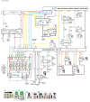
Does anyone know the pinout/description of the 2 connectors beside the inertia switch in the RH front kick panel (RH Drive). I did have a picture way back when of the colour codes and the connector.
I have soldered the connectors in the LH kick panel a few years back and want to do the same. I had in the back of my little head that one wire was relevant to the EAS inhibit switch (which is not working apart from the brake pedal)

I have hunted through RAVE but cant seem to find the descriptor

Cheers
 
The diagrams are in the 1997 version of RAVE.

1683020826390.png


1683020938385.png
 
Eas inhibit goes behind the LH kick panel. From memory, one of the connectors on the RH kick panel carries the ac/ hvac
Cheers, that connector burnt out a couple of years ago and I soldered it the same as the ones on the LH side, the only one I am not sure of is the one beside it.
 
Unusual to see colours on a P38 diagram, but as I said it's too small to make out detail and will not enlarge on my computer.

If you open the attached pic/file then press download on the menu top left of pic. then open the file you can enlarge it alot more.

J
 
its a PNG image it's the only images I find that doesn't leech colours over time ,the draw back is they are usually too large to post some times and compression software size reductions is limited
 
If you open the attached pic/file then press download on the menu top left of pic. then open the file you can enlarge it alot more.

J
Yes it enlarges but is just a blur. I still say it doesn't look like any P38 schematic that I have seen because of the colours which are like those used on the L322.
 
Back
Top