LT230 intermediate shaft bearing pre-load question

This site contains affiliate links for which LandyZone may be compensated if you make a purchase.

j_g_uk

Well-Known Member
Posts
224
Location
Fareham
I’ve tried asking this on another thread about my LT230 rebuild but it’s got buried and I would really appreciate some thoughts from anyone ‘in the know’.

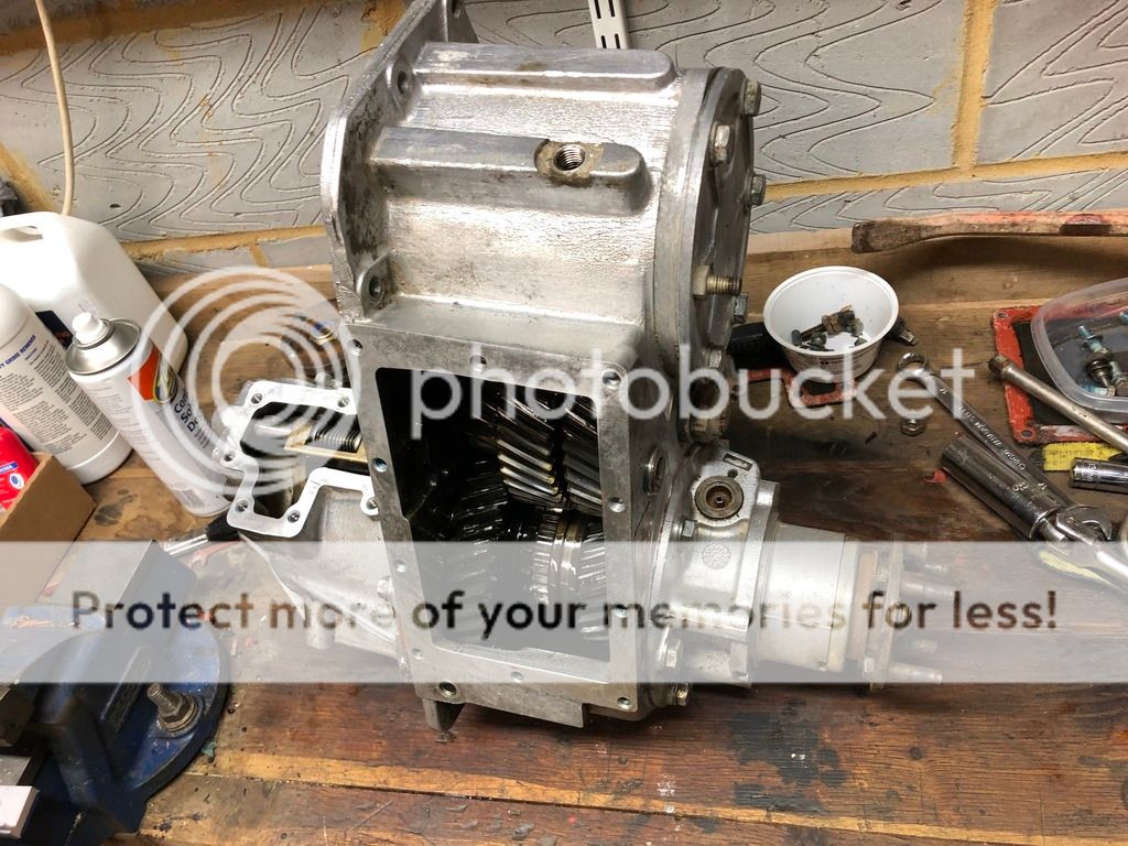
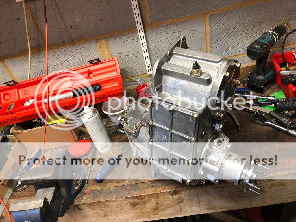
As I’m sure most people who have any experience of the LT230 transfer box will know, with the exception of the very early ones, the intermediate shaft has a once only collapsable spacer inside it and you set the pre load (according to LR) by measuring the increase in torque required to rotate the input shaft.

You can also set the pre load by using a string wound round the shaft and spring balance measuring the pull. Calculate the increase in pull required on the radius of the bit you’ve put the string round and you should end up with the same figure as the LR official method.

It’s also been suggested to me that winding the nut up until you lose all end float then adding another quarter turn will do the job.

There’s a video clip on YouTube that suggests LR technique ends up with too much preload, but presumably LR knew what they were talking about?

This is the first time I’ve rebuilt a LT230 so I’d like to get it right. I’ve got a torque meter and a spring balance and so could use any of the methods described. Has anyone ‘in the know’ got any thoughts please?

Or am I just worrying too much.
 
some mistake lrs 10 lbs in(lbs inches) for lbs ft,since they are taper bearings if you are refitting used bearings or adjusting out play just tightening nut till play is removed is ideal with new bearings you obviously want some preload to account for bearings running in, i use a torque meter and splined shaft to fit in input gear but string and a spring balance is fine too,diff gears must be in neutral, the range for the input gear was 5 -15 lbs in so 10 lbs in was the aim with a torque meter and 5-15 lbs on the spring balance,which is quite a range so obviously pin point accuracy wasnt necessary and shims came in 2 thou increments, not too tight or too loose, when setting intermediate bearings you adjusted the nut till the pull on the input gear increased by 8 lbs in or 8lbs pull give or take 3-4 lbs,that equates to .05mm or 2 thou preload and input and diff could be set using a dial gauge, we used to rebuild boxes for lr and these were the specs they gave us
ps the diameter of the shaft part of the input gear is 2 inches(which gives a measurement of lbs in on string wrapped round it) so you dont need a special tool just a hose clip or similar to attach one end of the string and a good few turns to account for the inertia in getting gear turning
 
Last edited:
That advice makes perfect sense. Thank you.

I’m replacing the bearings so they need some preload. (might as well replace while it’s in bits as even good quality bearings are relatively cheap and the tracks on the old ones are rather grey rather than shiny).

The one annoyance left is that the kit of bearings and gaskets I bought doesn’t have an ‘O ring’ for the shaft of the high low selector and the old one is flattened and needs replacing.

I’ll try and post some pictures.
 
If it's one of the cheaper kits you might want to consider replacing the input & output shaft seals with genuine or at least good quality.
You might find the gaskets a bit thin compared to genuine too.
 
If it's one of the cheaper kits you might want to consider replacing the input & output shaft seals with genuine or at least good quality.
You might find the gaskets a bit thin compared to genuine too.

I tried not to buy a cheap kit - by checking the the bearings are all recognised reputable makes. However despite my efforts, the gaskets are a bit thin...

The seals that were supplied seem to be reasonable quality. They're ribbed down the sides like the original fit ones if you follow what I mean. (I understand that some of the cheaper ones have plain sides.) The new flanges certainly seem to be a snug fit into them so I'm crossing my fingers that it will be very 'un-Land Rover like' and not leak...
 
Here's my first attempt at pictures on this forum. Some from stripping it down. I'll try and get some more of the build.

7755BBBF-DE7F-4A6B-A696-9C062F171B82_zpsu2aduuug.jpeg


E7A9EFDD-EE2A-4D71-A63B-788F67A9C664_zps6lbxfpgu.jpeg


45D59B9F-1D23-4FA2-B5D4-9BFC70B70B42_zpsjoyq6gxk.jpeg
317D9660-D371-4D19-9787-286E6876D706_zpsuikzrb7e.jpeg
9CE8250B-C44C-4AA4-B691-D7FBFD8FC650_zpskmsl59fp.jpeg
 
And to confirm, I've been setting the pre-load on the diff shaft with a DTI (measuring the end float and then adding 0.05mm to give the correct pre-load) I used a socket as a spacer down the end of the diff casing as I don't have a 'long reach DTI'. It's very convenient that the common DTI mount on a Magnetic Block is an 8mm thread exactly the same as the threads on the bearing housing.
 
And to confirm, I've been setting the pre-load on the diff shaft with a DTI (measuring the end float and then adding 0.05mm to give the correct pre-load) I used a socket as a spacer down the end of the diff casing as I don't have a 'long reach DTI'. It's very convenient that the common DTI mount on a Magnetic Block is an 8mm thread exactly the same as the threads on the bearing housing.
yes its the play plus the .05mm, once done diff should turn with a little resistance but not spin freely
 
Here's one of the intermediate gear bearings being tapped into place:

97E1E7EB-2728-4F34-A0DE-8130210862B8_zpsomeqhy2u.jpeg


And then driven home with the old bearing carrier/sleeve:

9ECFE573-D043-4AF9-B789-3F883A00E789_zpsgcm1kisx.jpeg


The old bearing outer gets 'just' caught in the housing but it comes out very easily. (I put a mole grip on it and extract it by tapping upwards on the mole grip.)
 
Having set the correct shims for the correct pre-load on the new taper bearings, the diff cover can be a real pain to get on, but after fiddling and jiggling, all the splines and bits and pieces line up and its time to finally fit new bolts with thread lock and torque them down.

6E66CF0B-B804-40DB-8D3B-A1E64031CB8A_zpsqc0qrnly.jpeg


It's starting to come together and look smart. Note the scar in the flange of the diff casing/bearing holder from some previous incident in a previous life of this LT230

4A33CB80-B588-42AD-A678-2E072A8B5B57_zps9hodgwen.jpeg
 
Here's one of the intermediate gear bearings being tapped into place:

97E1E7EB-2728-4F34-A0DE-8130210862B8_zpsomeqhy2u.jpeg


And then driven home with the old bearing carrier/sleeve:

9ECFE573-D043-4AF9-B789-3F883A00E789_zpsgcm1kisx.jpeg


The old bearing outer gets 'just' caught in the housing but it comes out very easily. (I put a mole grip on it and extract it by tapping upwards on the mole grip.)

Use a 1mm cutting disc on an angle grinder & cut through one side of the old race. Allows it to contract slightly as you use it as a drift & makes it easy to remove.
 
Good point and I've got a cutting disc and grinder so I might give it a go. I've got another LT230 to rebuild in a couple of weeks so I will have the benefit of the experience of working on this one...
 
Some more photos

New input gear (cross drilled) to replace the old one that wasn't cross drilled...

9CA4B9D1-F1C2-4C0D-9B6D-A679078BDE49_zpsquahm3ki.jpeg


Driving the new gears on the input shaft using the inner of one of the old bearings and a bit of hardwood and a soft faced hammer. The book says use a press, but they went on without too much fuss using this technique.
4DF7277C-882B-48FD-8319-C5DE979308FB_zpsym7stcw5.jpeg


Using the DTI to measure the end float before selecting shims to allow for 0.05mm pre-load. The thread on the DTI holder is a convenient 8mm metric and it screws into a 8mm hole nearby.

7CCE0666-361B-459C-98C2-8A7AAB7B1F65_zpshjltlykb.jpeg
 
6BDCB47D-241E-4125-90C3-8A4EF85C35AA_zpsfj4fjyex.jpeg


817F097D-5D44-4C8E-A349-69CB302A9E6A_zpsopha1mbg.jpeg


The finished article. I'm sorry that I didn't take any pictures of me pre-loading the intermediate shaft. I ended up using the string and spring balance technique, although I still have doubts as to how accurate I got it. I took all the end play out of the intermediate shaft and then by the time I'd wound another quarter turn on (or nearly) the spring balance had increased from 2 on the scale to 3 so I stopped... I say 2 on the scale as I am completely unconvinced that the scale in oz and lb's is accurate. I do know that I had to clamp the LT230 to the bench and use a 900mm breaker bar to wind the tension up on the nut... There's a very slight lumpiness to the gearbox now but I think that's normal for new bearings and shows that they are under some pre-load.

There was only one copper washer under the breather fastener and banjo so I assume there should be another between banjo and hi-lo selected shaft casing. I'll source one from somewhere.

In the both pictures above, you will see that it's got as temperature gauge sender. (or is it an 'over temperature warning light sender?) Bottom left in the second photo. The LT230 is going in my Defender and as you can see in the photo, I've plugged the hole with the old temperature sender unit. I assume there is no wiring in the harness or warning light on my Defender instrument cluster? I don't work the LR very hard except for the occasional towing of a trailer with one or two tonnes of soil or compost so I'm not really worried about oil temperature in the transfer box but I suppose it would be a 'nice to have' if the light was there.
 
Last edited:
its a temp warning light you probably have the wiring tucked near the rev light and diff lock wiring, they were generally only fitted for usa and jap markets
 
Back
Top