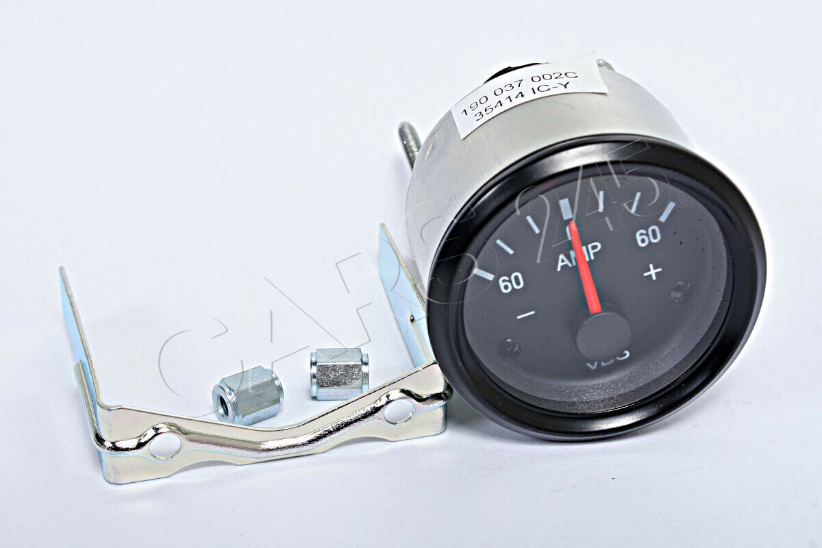
First of all many thanks to @Hicap phill for the voltmeter to finish my dash for my rebuild after the fire I can now put the dash and centre console all back together.
I had a bit of a play with it this morning to work out how to wire it in and in testing the needle goes off the scale on the gauge. What am I doing wrong?

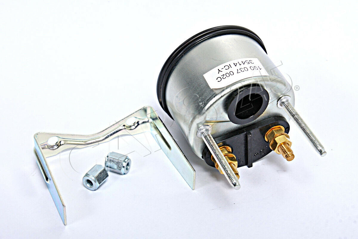
From this thread: link and from my testing I agree that the two terminal labeled 1 is for earth and 2 is for the 12v feed this would be ignition fed in the vehicle but for testing is direct to the battery. (both of mine are now male spade connections as one was broken and I have screw on male spaded on the shelf to repair but this should make no difference)
I have a 12 volt battery for bench testing that is 12.5 volts according to the multimeter.

From the way my old gauge worked I would expect 12.5V to be just under the central line as this is where it used to sit with the ignition on but no engine running, when running with the alternator power the gauge would then move to just over the centre line. However when connected to my test battery the gauge moves off the scale, see the video below:
I had a bit of a play with it this morning to work out how to wire it in and in testing the needle goes off the scale on the gauge. What am I doing wrong?
From this thread: link and from my testing I agree that the two terminal labeled 1 is for earth and 2 is for the 12v feed this would be ignition fed in the vehicle but for testing is direct to the battery. (both of mine are now male spade connections as one was broken and I have screw on male spaded on the shelf to repair but this should make no difference)
I have a 12 volt battery for bench testing that is 12.5 volts according to the multimeter.
From the way my old gauge worked I would expect 12.5V to be just under the central line as this is where it used to sit with the ignition on but no engine running, when running with the alternator power the gauge would then move to just over the centre line. However when connected to my test battery the gauge moves off the scale, see the video below: