P38A HEVAC Blend Motor Testing

This site contains affiliate links for which LandyZone may be compensated if you make a purchase.

pwood999

Well-Known Member
Full Member
Posts
4,813
Location
Near Heathrow.
Having sorted my Green P38 heater distribution motor & gears recently, it's now having issues with the blend motors. Firstly, it's not the flaps - they both move freely.

Left one is working fine when I power it with a 9V battery & measure the pot resistance. HEVAC sometings bitches, but cleaning the connector sorted that.

The problem child is the right blend. Found the potentiometer was giving intermittent readings, so took it out & measured it across the full range. Thorough cleaning & resoldering it to the PCB cured that. Moving the motor with 9V battery now giving smooth feedback from end to end, and expected partial range when re-installed (about 1.2k to 6.5k ohms). Plugging back into HEVAC results in a current fault & feedback stuck at 40%, so it now looks like connector issues to the motor.

Also ran the car and moved the motor using 9V battery. Vents go from hot to cold with no problem. Set it about 40% for now, so the air is cool but not too cold !!

New 16-way connector on order, so will be replacing that. Planning to check & re-solder the HEVAC side as well, but already did that back in January when dash was out.
 
Adding to above, I’m also thinking about how to measure the HEVAC output voltage in case the board has hardware fault. I have a spare with bad display so the main board from that might help.
 
I can give you details of the motor drive chips if it would help. Bad display? Not the ZEBRA strip which can be replaced?
Probably the zebra yes, but never got round tuit. Are the motors direct from the chip, or any output transistors ? Was gonna look myself, but if you already have the info ?
 
Last edited:
Direct from OP Amp driver chips. I'll dig the info out this evening.
It's raining again so here is the info on the chip that drives the blend and distribution motors.
L272 HEVAC chip.jpg

L272M pinouts.jpg


You can find the full spec on line.
 
Swapped over the main board from my spare HEVAC just now. Blend & Distribution all calibrate correctly & no faults. AC working well from hot to cold & vent selection as it should be.

Just for good measure I resoldered the 16-pin connector & Op-amps on the faulty board, but it still refuses to drive the right blend motor. Path from chip to the connector reads ok, so might try swapping the chip. Diagnosing further back is challenging because the PCB appears to be multi-layer, so tracing what drives the Op-amps is unclear.

The chip circled in picture connects to right-blend motor, so I'm assuming that's the fault.

IMG_1017.jpg
 
Swapped over the main board from my spare HEVAC just now. Blend & Distribution all calibrate correctly & no faults. AC working well from hot to cold & vent selection as it should be.

Just for good measure I resoldered the 16-pin connector & Op-amps on the faulty board, but it still refuses to drive the right blend motor. Path from chip to the connector reads ok, so might try swapping the chip. Diagnosing further back is challenging because the PCB appears to be multi-layer, so tracing what drives the Op-amps is unclear.

The chip circled in picture connects to right-blend motor, so I'm assuming that's the fault.

View attachment 319634
Easy enough to check the output. I have had to replace one L272 which is why I have the data sheets.
 
Yes but eBay is quicker & easier than China. RS & Farnell postage is silly for a few op-amps, although they do stock the dual 16way+12way socket on the HEVAC PCB if I ever want to change that.
 
After doing the chip replacement a while back on my spare HEVAC, got back on the HEVAC in the P38 again today. Replaced the 16-pin connector completely, and then tested all three motors using 9V battery & multimeter.

LH Blend pot goes from 1.5k to 8.4k (maybe pot is 1 tooth out ?)
RH Blend pot goes from 600R to 7.7k
Distribution goes through the correct range of movement (didn't check ohms) & can force using Nanocom to all positions.

Then did calibration using Nanocom, which seems to complete ok, with no errors reported. But still getting faults on LH side, and cannot seem to move it using Nanocom utility.

Guess it's time to swap the HEVAC with the repaired one, and see if that works ??

Also noticed the heater core temp is wrong again (-12degC).

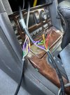
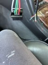
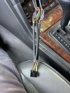
IMG_2809.JPGIMG_2810.JPGIMG_2811.JPG
 
Last edited:
Update on this. Replaced the connector on the heater core sensor, so now that reads correctly (90% of the time, but occaisionally jumps to -20degC !).

Re-visited the HEVAC control, and confirmed no voltage out of the L272M driver chip. Replaced it with a new one, but still no output. It does seem to appear the HEVAC has other faults on the board.

While testing, I noticed the Nanocom Inputs for all the switches detects most of them correctly, BUT the temp up-down switches have the Left & Right the wrong way. Left switch shows as Right in Nanocom, etc.

Various people have seen similar for the ABS sensors. It does seem one of the BBS programmers does not know their left from right !! Updating it to latest 1.40 release now, and will check again !!
 
Does anyone have a spare working HEVAC going cheap ? Don't mind if it has pixely display, because I have a spare Zebra strip to sort that.
 
Also did some tests on my spare heater box & motors today. Tested each motor with 9V battery & multimeter on the pots.

They do seem to vary a bit, but we have to assume the HEVAC simply tests the voltage across the pot across the range when calibrating ?

At least it's a useful guide for testing them.

1755702727523.png
 
Also did some tests on my spare heater box & motors today. Tested each motor with 9V battery & multimeter on the pots.

They do seem to vary a bit, but we have to assume the HEVAC simply tests the voltage across the pot across the range when calibrating ?

At least it's a useful guide for testing them.

View attachment 348046
The measured pot value should be nearly the same depending on the quality of the pots, they are not 1% devices but mine were within 5%.
 
Took the right blend apart to check. Def says 10K on the pot & measures 12.3k on terminals !! Bit more than 5%, but hey ho, if the HEVAC uses it as a voltage divider then should be ok.

Will see what happens with the "new" HEVAC.
 
Took the right blend apart to check. Def says 10K on the pot & measures 12.3k on terminals !! Bit more than 5%, but hey ho, if the HEVAC uses it as a voltage divider then should be ok.

Will see what happens with the "new" HEVAC.

Maybe the track is so worn that the resistance reads high. personally I would change it because the reading from the divider at any given point will be incorrect so the flap will not be where the HEVAC wants it to be.
 
Either of those sounds more likely. As both the set in the car, and these go through the resistance range smoothly, will try the replacement HEVAC first. If required, I have 5 spare pots ready. Did one in the other car a while back, but had to remove glovebox & airbag to get to it.
 
Back
Top