Freelander 2 (LR2) Freelander 2 DIY Rear Diff Rebuild

This site contains affiliate links for which LandyZone may be compensated if you make a purchase.

Nodge68

Well-Known Member
Posts
32,954
Location
Cornwall
This guide will be serialised, as time allows.

I've decided to do a full guide on what is involved with repairing the Freelander 2 rear differential.

These diffs do have a weakness, where the pinion tail bearing (closest to the Haldex) fails prematurely. The bearing making itself known by generating a whining or grinding noise, audible coming from the back of the vehicle.

It's this common issue, my own diff failure prompting me to do this DIY repair guide.

Before deciding to pull the diff out the vehicle, it is sensible to remove the oil from the diff, so it can be checked for metallic particulates. Unfortunately the diff noise could also be confused with wheel bearing noise, so the way to identify the diff is to look at the oil.

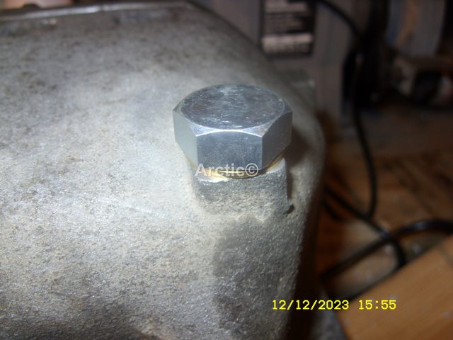
Be aware that this diff doesn't have a drain plug, which means the oil needs to be removed with a syringe or electric pump, made for the purpose.

More to follow.
 
Last edited:
Rear diff removal.

The rear diff on the FL2 isn't very difficult to remove.
There are several ways to do it, but I think the easiest way is to use the method I used, which will be detailed here.

First off, support the vehicle in the air on axle stands. I actually used 4 stands in total, a I hate getting under a vehicle unless its very securely supported.
I used 2 stands under the chassis rails, behind the rear wheels, and another 2 under the rear sill jacking points.
I used various bits of wood to adjust the stands, so all 4 got to share the weight of the vehicle.

Once supported, I removed the rear wheels, to gain access to the suspension link bolts. I removed all 3 link bolts, which allows the rear hub to swing outwards, enabling the drive shaft CV joint to be released from the diff. The RHS (UK Driver's side) CV is easy to remove from the diff, requiring a large flat screwdriver, pry bar or even a car tyre lever, which is simply used as a lever between the CV joint and diff case. This pops the locking C ring, allowing the whole drive shaft to be withdrawn from the diff spline, as the hub assembly is pulled outwards.
I used a bungee strap to keep the shaft off the floor, and a plastic bag over the spline to keep it clean.
I repeated the procedure for the LHS (UK passenger side), although the CV joint is obscured by the diff casing extension, so a short stout screwdriver was used, the the access hole in the diff casing extension for this purpose.

Next is the propshaft to Haldex to flange bolts, of which there are 6 to remove. Each pair of bolts is passed through a curved washer, forming 3 groups of 2 bolts. This is the same design as the FL1 IRD to propshaft joint, and also the same as many other LR vehicles. The bolts are supposed to replaced on reassembly, so get some before starting work.

It should be noted, that the LR manual says these bolts need to be replaced, but I figure a dab of thread lock will do the trick, however I did replace them, as I know they'd been undone at least once before I got the vehicle.

I marked the propshaft relitive to the Haldex flange, so I could refit it in the same position it was removed from. As to whether this is necessary, I can't say, but that's what I did.

I found the easiest way to get the propshaft out the Haldex flange (it sticks quite tightly), was to free the front of the diff from its aluminium support, so it has some free space. To do this I removed the Haldex plug, then put a jack under the diff casing to take the weight. Next I removed the four 10mm head bolts from the underside of the support member.
I next removed the LH 18mm head bolt from the end of the support member, and released the RH bolt a couple of turns. This allows the support member to swing down and out the way.

With the support out the way, I lowered the jack a couple of inches (50mm), which would give sufficient room for the propshaft to be withdrawn from the Haldex flange. I then used a short stout chisel held at an angle on the propshaft coupling, and struck it with a hammer. It took a couple of firm taps, and the propshaft coupling popped out the Haldex flange.
Once the propshaft was free from the Haldex, I just let the propshaft hang, as it wasn't in the way.

At this point there's only two more bolts to keeping the diff in car.
These bolts are accessible from exhaust side of the rear subframe, so require the rear box to be unhooked from its three rubber hangers. This job was made easy with a quick spray of silicone lubricant, after which the hangers can be slipped off the pegs with the aid of a screwdriver.
The exhaust can then be lowered to the floor, so access to the two 15 mm rear diff bolts can be made.

After the first bolt was out, I put a screwdriver in the bolt hole, simply to provide a bit of support, for when the final bolt was removed.
Once the last bolt was out, the only thing keeping the diff in place was the jack and the screwdriver. I then slowly lowered the jack about 4 inches (100mm) so I could get to the two breather pipes.
Once those are pulled off, the screwdriver was removed, so rear diff could be lowered to the ground. From there it was withdrawn out from behind the LH (UK passenger side) rear hub assembly.
 
Last edited:
Here's a collection of pictures of the diff being removed.
20210206_130710.jpg
20210109_155106.jpg
20210109_131610.jpg
20210109_141612.jpg
20210109_133721.jpg
20210109_134330.jpg
20210109_151446.jpg
20210109_151436.jpg
20210109_155037.jpg
20210206_110412.jpg
20210109_162147.jpg
20210109_155300.jpg
 

Attachments

  • 20210109_131610.jpg
    20210109_131610.jpg
    393.9 KB · Views: 507
  • 20210109_162147.jpg
    20210109_162147.jpg
    215.5 KB · Views: 318
  • 20210109_151446.jpg
    20210109_151446.jpg
    417.7 KB · Views: 316
Last edited:
haven't you rebuilt that Diff yet, just wondering cause if it isn't the rear bearing that has gone then it will be the diff and a step by step guide would be useful. :)
 
haven't you rebuilt that Diff yet, just wondering cause if it isn't the rear bearing that has gone then it will be the diff and a step by step guide would be useful. :)

Yes, it was done before I started this thread. Unfortunately life got in the way and my old brain forgot about doing the thread. :(

I'll update it ASAP. ;)
 
Hi
I’d be interested to see how this went, paid £350 to get it done last year wondering if I wasted my money, I have a small leak from what looks like a blank on the Haldex and now getting some bumping in low gear when turning left ?
 
I will complete this thread, unfortunately I never seem to have time.

The diff isn't that difficult to rebuild, but it does need a special tool to remove and refit the bearing retainer nut, otherwise it's pretty straightforward.

Interestingly mine has the same thumping as Haldex engagement occurs, which I'd put down to the incorrect fluid being used in the Haldex before I got it.
Maybe it's something more sinister though, I hope not, as I'm sure the diff rebuild went perfectly.
 
Thanks ,
I’m thinking possibly a low oil level in the haldex,I’ll top up and check, not sure how the haldex functions but I’m assuming a lack of oil pressure or possibly blocked filter
 
Thanks ,
I’m thinking possibly a low oil level in the haldex,I’ll top up and check, not sure how the haldex functions but I’m assuming a lack of oil pressure or possibly blocked filter

Mine I believe has been damaged by the incorrect oil being used. So I'm going to pull the fuse for a while, so as to avoid damage to the PTU, which has already been replaced on mine.

Judder can be the controller valve faulty or blocked, or it's oil way blocked.

However if ordinary gear oil has been used (mine had something like EP90 in it), then unfortunately the clutch pack is ruined, and will need replacing. :(
 
Rear diff removal.

The rear diff on the FL2 isn't very difficult to remove.
There are several ways to do it, but I think the easiest way is to use the method I used, which will be detailed here.

First off, support the vehicle in the air on axle stands. I actually used 4 stands in total, a I hate getting under a vehicle unless its very securely supported.
I used 2 stands under the chassis rails, behind the rear wheels, and another 2 under the rear sill jacking points.
I used various bits of wood to adjust the stands, so all 4 got to share the weight of the vehicle.

Once supported, I removed the rear wheels, to gain access to the suspension link bolts. I removed all 3 link bolts, which allows the rear hub to swing outwards, enabling the drive shaft CV joint to be released from the diff. The RHS (UK Driver's side) CV is easy to remove from the diff, requiring a large flat screwdriver, pry bar or even a car tyre lever, which is simply used as a lever between the CV joint and diff case. This pops the locking C ring, allowing the whole drive shaft to be withdrawn from the diff spline, as the hub assembly is pulled outwards.
I used a bungee strap to keep the shaft off the floor, and a plastic bag over the spline to keep it clean.
I repeated the procedure for the LHS (UK passenger side), although the CV joint is obscured by the diff casing extension, so a short stout screwdriver was used, the the access hole in the diff casing extension for this purpose.

Next is the propshaft to Haldex to flange bolts, of which there are 6 to remove. Each pair of bolts is passed through a curved washer, forming 3 groups of 2 bolts. This is the same design as the FL1 IRD to propshaft joint, and also the same as many other LR vehicles. The bolts are supposed to replaced on reassembly, so get some before starting work.

It should be noted, that the LR manual says these bolts need to be replaced, but I figure a dab of thread lock will do the trick, however I did replace them, as I know they'd been undone at least once before I got the vehicle.

I marked the propshaft relitive to the Haldex flange, so I could refit it in the same position it was removed from. As to whether this is necessary, I can't say, but that's what I did.

I found the easiest way to get the propshaft out the Haldex flange (it sticks quite tightly), was to free the front of the diff from its aluminium support, so it has some free space. To do this I removed the Haldex plug, then put a jack under the diff casing to take the weight. Next I removed the four 10mm head bolts from the underside of the support member.
I next removed the LH 18mm head bolt from the end of the support member, and released the RH bolt a couple of turns. This allows the support member to swing down and out the way.

With the support out the way, I lowered the jack a couple of inches (50mm), which would give sufficient room for the propshaft to be withdrawn from the Haldex flange. I then used a short stout chisel held at an angle on the propshaft coupling, and struck it with a hammer. It took a couple of firm taps, and the propshaft coupling popped out the Haldex flange.
Once the propshaft was free from the Haldex, I just let the propshaft hang, as it wasn't in the way.

At this point there's only two more bolts to keeping the diff in car.
These bolts are accessible from exhaust side of the rear subframe, so require the rear box to be unhooked from its three rubber hangers. This job was made easy with a quick spray of silicone lubricant, after which the hangers can be slipped off the pegs with the aid of a screwdriver.
The exhaust can then be lowered to the floor, so access to the two 15 mm rear diff bolts can be made.

After the first bolt was out, I put a screwdriver in the bolt hole, simply to provide a bit of support, for when the final bolt was removed.
Once the last bolt was out, the only thing keeping the diff in place was the jack and the screwdriver. I then slowly lowered the jack about 4 inches (100mm) so I could get to the two breather pipes.
Once those are pulled off, the screwdriver was removed, so rear diff could be lowered to the ground. From there it was withdrawn out from behind the LH (UK passenger side) rear hub assembly.[/QUOTE

Hi Nodge,
I'm thinking of attempting this, a couple of questions
1. When removing the drive shaft from the diff does it just pop out ,apparently theres a clip around the shaft?
2. You mention a special tool to refit the bearing retainer nut, is this absolutely necessary?
3.any recommendation on a good supplier of a reconditioned diff with upgraded nose bearings?

1:
The propshaft is centred to the diff flange within a cup. It is a mild interference fit, but is easily removed as there are 2 access holes on the diff side to tap it free with a suitably sized drift, obviously remove the 6 Torx bolts first. The diff front mount needs to be released and the diff allowed to lower a bit (keep it supported) so there's enough room for the prop flange to come out.
Technically the bolts are throw away items, but a dab of thread lock on refitting will work just as well. The bolts aren't tightened to yeald in this installation, so reusing them seems ok.

2:
Unfortunately the special tool is a must, as it holds the locking nut and spline at the same time. I've seen people do the job without the tool, but it's not easy, especially as the crush tube takes several hundred Nm of torque to crush down.

3:
Bell Engineering are the guys to use.
However I don't believe the larger bearing is necessary for a permanent fix. The diff was assembled incorrectly to start with (the bearing pre-load was way too high in the factory build) so as long as the diff is built correctly, a larger bearing is theoretically not needed. Even factory diffs with the larger tail bearing fail.
However Bell do use the larger bearing, so presumably they've done some testing on the subject.
Me, I'd just rebuild it with a quality bearing, not the Indian sourced bearing the factory fitted, and set the pre-load as per the TSB specification.
 
Thanks again,
Think I’ll go with a reconditioned unit,much simpler.
I think this fills in the blanks,(in Russian but self explanatory)
 
Got the diff off this evening and will proceed to replace the bearings in the next few day/weeks. Couple of questions Nodge if I may. How did you measure the preload/torque on the pinion bearing (did you use the LR special tool) and did you use the special support frame for the diff. If not how did you support the diff. Don't want to go to the expense of buying these special tools if I don't have to.
 
Couple of questions Nodge if I may. How did you measure the preload/torque on the pinion bearing (did you use the LR special tool) and did you use the special support frame for the diff. If not how did you support the diff.

I measured the pre-load by feel. I've built many diffs and other taper bearing packs over the years, so can tell when it feels right.
For this diff, I set the pre-load to a couple Nm, which is about the same torque as screwing in a No8 wood screw.

No need for anything elaborate to support the pinion while assembling the bearing pack. I just used a suitable length of softwood, which did the job just fine.
The diff is machined in such a way, that the pinion gear is always in the correct place on the crown wheel, so no setting up is needed.

You have to use the special pinion nut drive tool, but that's the only special tool needed.

Hi John.1
Do you have a link for the special tool that is needed above, did you also take anymore photos when repairing the bearing etc.

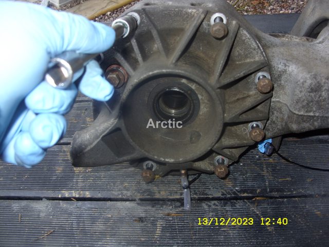
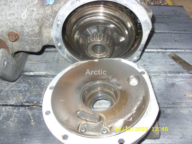
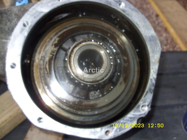
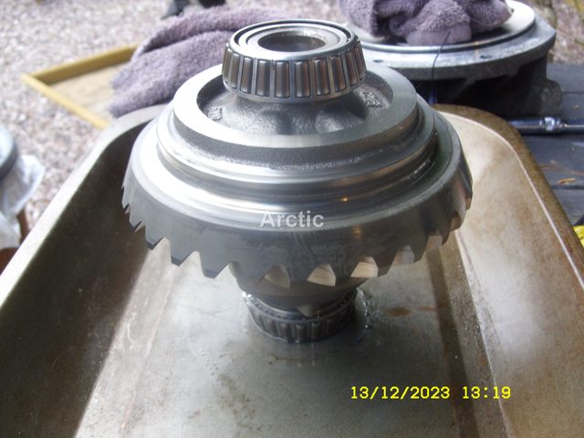
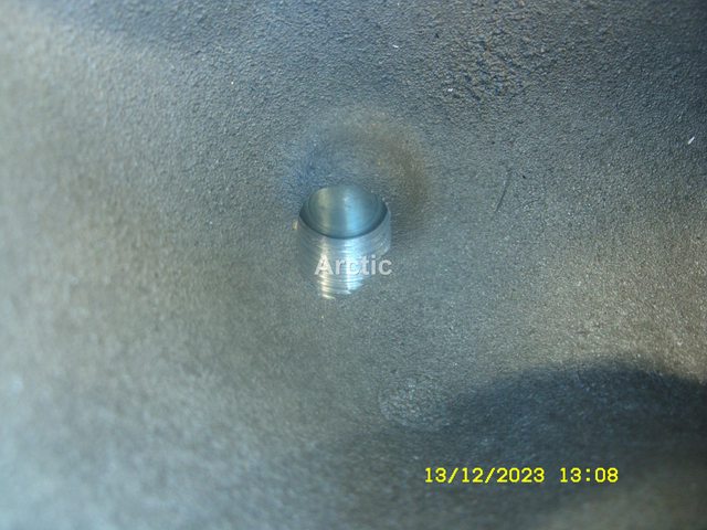
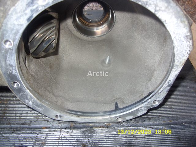
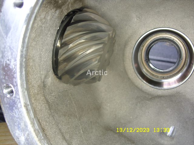
I took my spare diff apart yesterday after i drilled the drain hole in it, couple of photos below, i am doing a thread on it later today or to night.
T8P6FH3l.jpg
1

Keiq4t1l.jpg
2

zQhYCE1l.jpg
3

VjNCBHjl.jpg
4

iJGTgShl.jpg
5

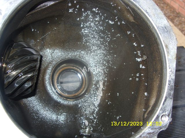
Alloy swarf from drilling the drain hole.
4p4EXJ6l.jpg
6

PNQwhcvl.jpg
7

D5UQgx3l.jpg
8

O0AeiuYl.jpg
9

cleaned out.
ohtNlrCl.jpg
10

CFwMCSTl.jpg
11
 
Back
Top