Lukas430000
Active Member
- Posts
- 88
- Location
- Livingston, Scotland
Hello all.
I am new to this and Happy Hippo family. Quick question to all who can help. I have found set of speedo clocks for my landy and I am not sure if they fit. Just sent message to ebay seller asking what year and model they coming from so will try update. they are slightly different to mine. Mine have fuel gauge on the right side without wee arrow The new ones have fuel gauge onnthe left side. Iam not sure if they fit my one.
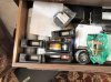
Mine:

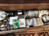
New ones:

And my question is if they will fit MY 2000
Best regards
Luk
I am new to this and Happy Hippo family. Quick question to all who can help. I have found set of speedo clocks for my landy and I am not sure if they fit. Just sent message to ebay seller asking what year and model they coming from so will try update. they are slightly different to mine. Mine have fuel gauge on the right side without wee arrow The new ones have fuel gauge onnthe left side. Iam not sure if they fit my one.
Mine:
New ones:
And my question is if they will fit MY 2000
Best regards
Luk
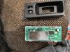
 . my fuel sender have a four pin square plug so I wonder if its possible to somehow retrofit the light for fuel.