Engine just conked out!

This site contains affiliate links for which LandyZone may be compensated if you make a purchase.
Couple of other things that no one has mentioned yet.
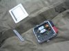
Don't forget oil in the injector loom problem. Usually this just results in poor running, but can make the engine cut out, as happened to me. You can see oil in the multiplug where the injector loom enters the engine. It is at the front of the engine on the driver's side just under the rocker cover. Or, if it's been leaking for a long time, it might have crept all the way back to the red plug of the ECU under the driver's seat.

Noted, thanks. The mechanic I consulted told me about this business of oil seeping back to the ECU but the wires at that end are absolutely clean. The crank sensor and its plug & wires at the engine end, OTOH, are *VERY* oily for some reason. But I don't see how that could cause the abrupt failure I experienced. I'll have a better look later; it's cloudy today which makes for better visibility in the shadowy areas under the eaves of the rocker cover. At present I'm giving the battery a much needed charge as it's had nothing but load put on it over the last few days...
 
Update: rain stopped play. I had to foreshorten the battery recharging and postpone further investigation for today as it doesn't look like it's going to improve before tomorrow morning. Tomorrow PM I *may* have a little spare time, but more realistically it'll be Monday before I get to grips with this again seriously. But we'll see.....
 
Noted, thanks. The mechanic I consulted told me about this business of oil seeping back to the ECU but the wires at that end are absolutely clean. The crank sensor and its plug & wires at the engine end, OTOH, are *VERY* oily for some reason. But I don't see how that could cause the abrupt failure I experienced. I'll have a better look later; it's cloudy today which makes for better visibility in the shadowy areas under the eaves of the rocker cover. At present I'm giving the battery a much needed charge as it's had nothing but load put on it over the last few days...

if the oil has got inside the crasnk sensor it could corrupt the signal from sensor to ecu, which without a crank signal the ecu will shut down
 
if the oil has got inside the crasnk sensor it could corrupt the signal from sensor to ecu, which without a crank signal the ecu will shut down

I'm not quite sure what you mean by "corrupt" in this instance. The signal from the sensor is analogue, not digitally-encoded.
I've made some further tests today which point towards a blown ECU. Follow-up in a few mins....
 
Greetings, gentlemen,

Right, I've done a few more tests today:

1. removed the injectors wiring plug where it attaches at the front of the rocker cover. Placed a 500 ohm resistor across the plug terminals for cylinder number 1 to simulate the rough load an injector solenoid might give rise to. Attached 'scope probe across resistor. Cranked engine over: dead. Switched resistor over to another cylinder's injector connections which uses a different return path to the ECU just to be sure. Cranked over: dead. In view of this there seemed little point in checking for fuel pressure, though of course I would have done this eventually if necessary once the non-firing injector issue had been sorted.

2. Checked the four individual grounds to that connect from the black ECU plug to a star ground which I'd previously overlooked: all fine.

3. Hooked the scope up across the crank sensor wires where they enter the ECU with the ECU still attached. Cranked engine: 6V p-p signal observed.

I therefore conclude, in the absence of any contrary intelligence anyone may put forward, that the ECU has sadly passed away. Have I missed anything?
Your thoughts?
 
that 6V is not good acording to the sensor's description in RAVE, it should have 6-6.5V when rpms are above 1000 and 2-3V while cranking, the timing is dependent on it's signal so even if it's high it's not good... you can get the description in RAVE
better check with a known good or new sensor before you blame the ECM
Crankshaft speed and Position (CKP) sensor
The CKP is located in the transmission housing with its tip adjacent to the outer circumference of the flywheel. The
CKP sensor works on the variable reluctance principle, which sends a signal back to the ECM in the form of an ac
voltage.
The ECM uses the signal from the CKP for the following functions:
l To calculate engine speed.
l To determine engine crank position.
l To determine fuel injection timing.
The CKP sensor works as a Variable Reluctance Sensor (VRS). It uses an electromagnet and a target ring to generate
a signal. As the target ring passes the tip of the CKP sensor the magnetic field produced by the sensor is cut and then
re-instated. The ECM measures the signal as an ac voltage.
The outer circumference of the flywheel acts as the target ring for the sensor. The flywheel is divided into 36 segments
each of 10. 31 segments have drilled holes and 5 segments are spaces. This equals 360 or one engine revolution.
The 5 spaces correspond to the TDC position of the 5 cylinders, this allows the ECM to control fuel injection timing
for each of the cylinders.
Input/Output
The two pins on the sensor are both outputs. The ECM processes the outputs of the sensor. To protect the integrity
of the CKP signal an earth shield or screen is used.
The ECM measures the outputs from the CKP. The ECM measures the positive signal from the CKP at pin 13 of ECM
connector C0158. The ECM measures the negative signal from the CKP at pin 36 of ECM connector C0158. The earth
path is via pin 16 of ECM connector C0158.
Voltage generation from the CKP sensor is relative to engine speed. The values expected from a good CKP sensor
are as follows:
l 2 to 3 volts with engine cranking.
l Rising to 6 to 6.5 volts from 1000 rev/min upwards.

The above readings are dependent upon correct air gap between the tip of the CKP sensor and the passing teeth of
the reluctor ring.

The CKP sensor can fail the following ways or supply incorrect signal:
l Sensor assembly loose.
l Incorrect spacer fitted.
l Sensor open circuit.
l Sensor short circuit.
l Incorrect fitting and integrity of the sensor.
l Water ingress.
In the event of a CKP sensor signal failure any of the following symptoms may be observed:
l Engine cranks but fails to start.
l MIL remains on at all times.(on D2)
l Engine misfires (CKP sensor incorrectly fitted).
l Engine runs roughly or even stalls (CKP sensor incorrectly fitted).
 
With the greatest respect, I'm not convinced. With a passive system like this it's really not feasible for the transducer involved to generate MORE than the expected voltage. The most likely explanation is a difference in measurement methodology between the Rave people and me. My system put an imperceptible load on what is a high impedance signal source - therefore not loading it down by any meaningful degree. If the Rave lot had used an analogue milivoltmeter to take the measurement on this delicate source, then 2-3V is exactly what I would expect to see. Or maybe they're talking about the rectified voltage which would be half of 6V = 3V. Again, normal. Also, these ropey analogue signals are passed through a Schmidt trigger to turn them into ultra-clean, nicely shaped pulses and it's these pulses that the ECU deals with.
Any other suggestions?
 
Actually, on re-reading what you posted from Rave, our readings do appear to concur. They're talking about the separate measurement of negative and positive-going peaks, which will be 3V.
The sensor is fine.
 
Just to clarify what I mean in my previous post: if the ground wire to the sensor is discontinuous the waveform presented to the ECU will not be ground referenced; it will float and not provide a readable value voltage. This is the wire I referred to some time ago that looks like it's been pulled and has half an inch of insulation missing from it, so it's worth double-checking!
 
yes, you are right... the conclusion is that without a tester you are quite "blind" now cos it's certain that the ECM doesnt open the injectors and you can't try a different ECM without it anyway

what you can try as a desperate last test as i see you know electronics is to open the ECM and figure out somehow with your oscilloscope if those great capacitors(pic attached) are working as they should cos as i said in older posts the "topside switch failure" is quite common and that's what happens when one of them is fubar'd, engine doesnt run and that fault code is stored...i can't tell you what should you get as i have testers and didnt bother to use the oscilloscope on them... if the part number on them is faded the one near the margin is PEH169PA410AQ the other close to the middle is PEH169KE433AQ, they were originally made by motorolla or phillips very hard to find
 

Attachments

  • Topside switch capacitors.jpg
    Topside switch capacitors.jpg
    6.9 KB · Views: 402
Have you tried the fuel cut off solenoid on the bulkhead? Designed to turn the fuel off in case of an accident but could have tripped.
 
I think a further clarification may be in order here for the sake of completeness.
I checked the DC resistance of the crank sensor (1.2k ohms)
I also have now checked the sensor's output voltage (~6VAC p-p)
What I have not yet checked is that this signal is ground-referenced. I now need to test for a positive peak signal of ~3V *WRT ground* on pin 13 and a negative peak signal of ~3V *WRT ground* on pin 36. If these signals are present, then the sensor is fully operational and the prime suspect for failure once again becomes the ECU.
If the voltage turns out to be floating, of course, then I'll owe Sierrafery a very large beer. Tune in tomorrow to find out, kids. :)
 
Have you tried the fuel cut off solenoid on the bulkhead? Designed to turn the fuel off in case of an accident but could have tripped.

I haven't to be honest. I'm not sure the ECU would deal with this eventuality by cutting the signals to the injectors, you see.
But I'll add to my list of unlikely-but-worth-checking-nevertheless possibilities, cheers.
 
yes, you are right... the conclusion is that without a tester you are quite "blind" now cos it's certain that the ECM doesnt open the injectors and you can't try a different ECM without it anyway

what you can try as a desperate last test as i see you know electronics is to open the ECM and figure out somehow with your oscilloscope if those great capacitors(pic attached) are working as they should cos as i said in older posts the "topside switch failure" is quite common and that's what happens when one of them is fubar'd, engine doesnt run and that fault code is stored...i can't tell you what should you get as i have testers and didnt bother to use the oscilloscope on them... if the part number on them is faded the one near the margin is PEH169PA410AQ the other close to the middle is PEH169KE433AQ, they were originally made by motorolla or phillips very hard to find

Well you're obviously a very highly clued-up person yourself and I'm very grateful for these bones you keep throwing me. Two heads are invariably better than one in this situation!
As you've probably gathered, I'm old school. It doesn't hit me as the first solution to go out and buy a code-reader or even try to borrow one. A diesel engine is a very, very simple machine at heart and it should be readily possiblel to fix a problem such as mine without recourse to de-coding error logs. If all this vehicle's electronics/electrics were laid out before me on my bench I'd find this fault in 5 minutes flat at most. It's only the fact that it's in an automotive setting that's quering my pitch and making things difficult. I haven't even got anyone to turn the ignition key while I check readings, which adds another layer of difficulty on.
Luckily I enjoy troubleshooting and fault-tracing so this is no work for me. It's quite fun, actually. :)
 
I haven't to be honest. I'm not sure the ECU would deal with this eventuality by cutting the signals to the injectors, you see.
But I'll add to my list of unlikely-but-worth-checking-nevertheless possibilities, cheers.

Not sure how it works tbh, but got to be worth eliminating
 
unfortunately for you the Td5 has a quite complicated electronic management and it's very hard to diagnose any management issue without proper tester... or it can be very laborious without any result...imagine how easy it would have been if you had one... by now it could have been fixed:cool:
 
Back
Top