Defender front brake pipe replacement

This site contains affiliate links for which LandyZone may be compensated if you make a purchase.

angusb

New Member
Posts
7
Location
West Country
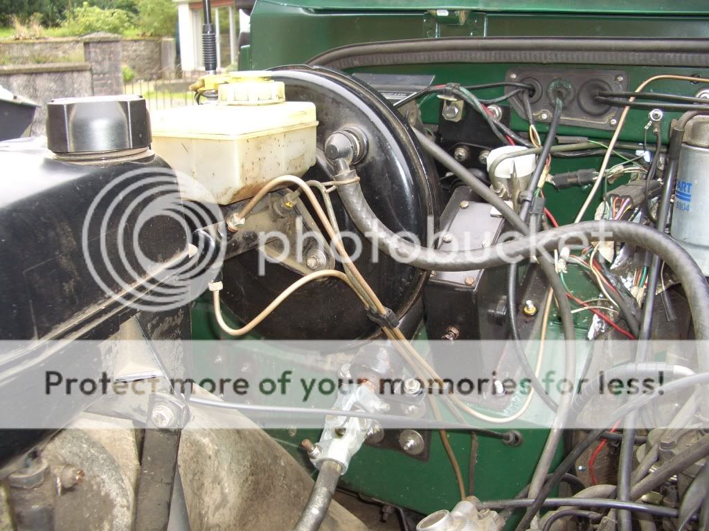
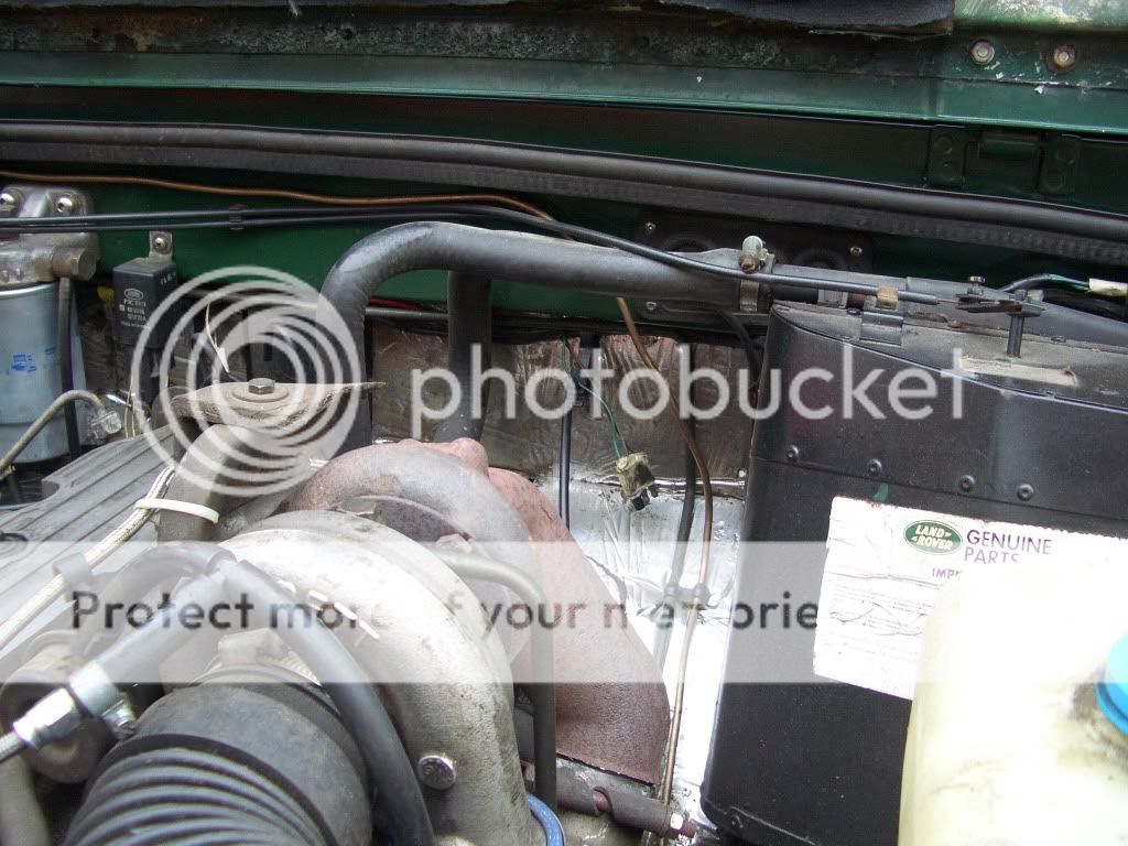
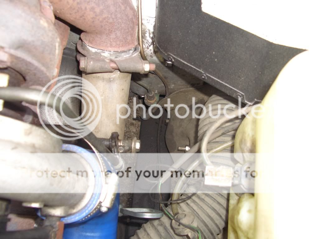
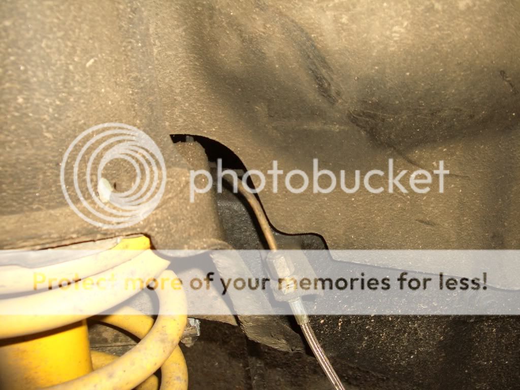
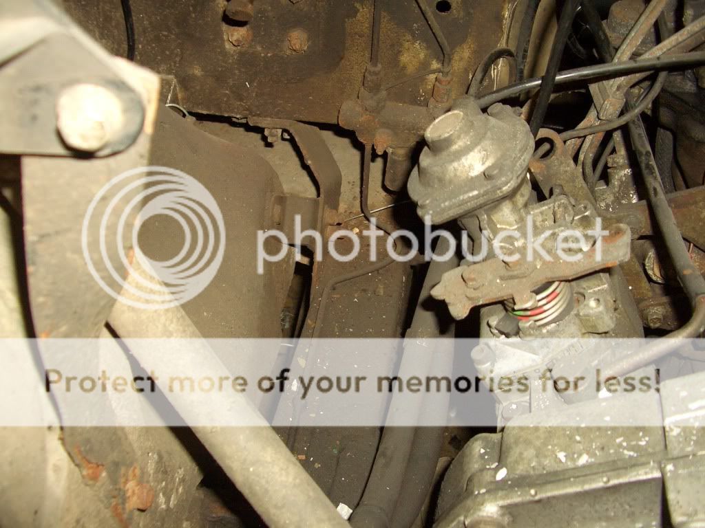
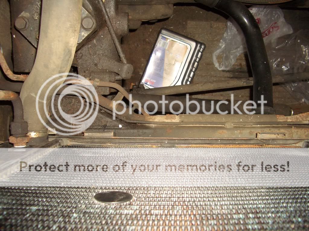
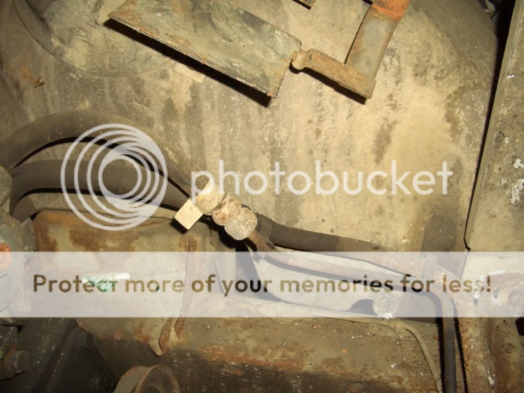
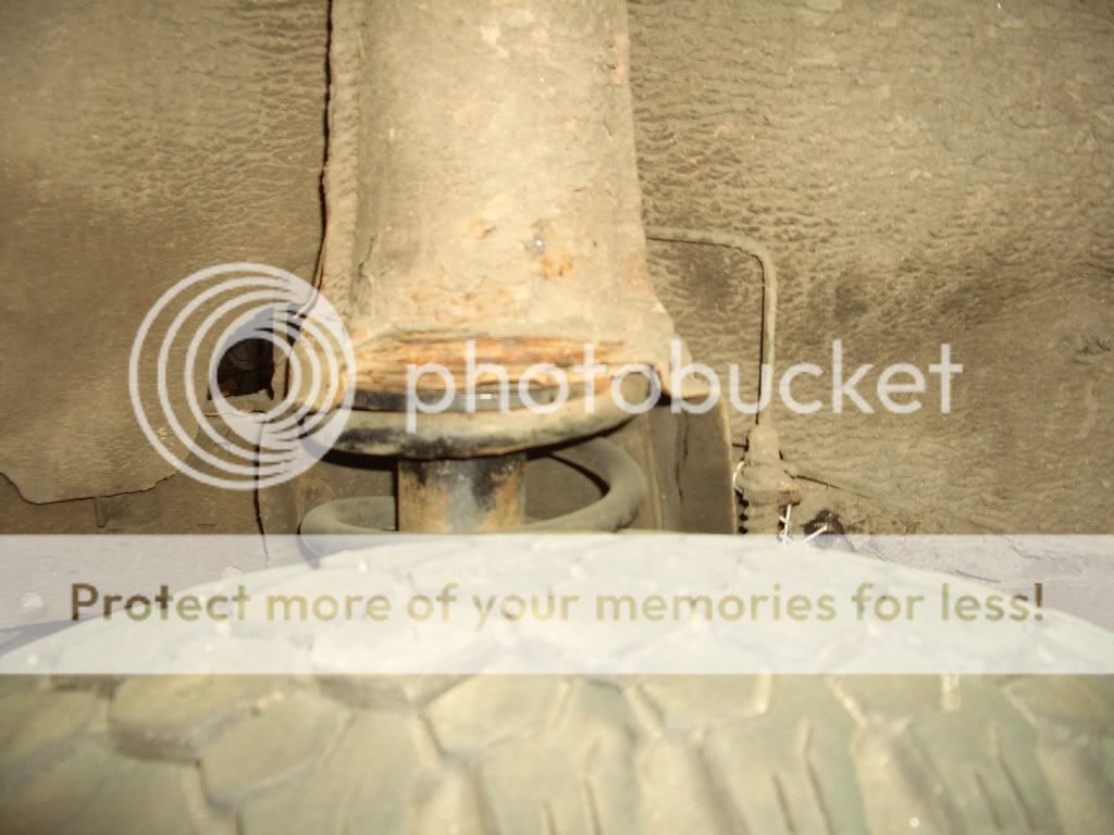
I need to replace the long pipe that goes from the T-piece on the driver's side of the bulkhead to the front passenger side flexi/caliper as it is corroded. What do I need to remove to do this? It looks like I'm going to have to take the inner wings off to get the old pipe out and the new one in. I'd like to keep the old pipe in one piece so I can copy it to make up the new one.
 
Ye don't need to remove the wing and the pipe is held in with clips. You will need to undo the flexi pipe and then undo the nut holding the old metal pipe to the bracket. It might be a good idea to unscrew the reservoir lid, stick a piece of plastic bag over the hole and screw the lid back on to help stop too much fluid leakin' out. Might be a good idea to clamp the flexi hose as well. If ye don' have a flaring kit and connectors for the new (copper) pipe, then get yer local indy or garage to knock ye a new pipe up;)
 
So would I be able to get the old one out by pushing the bit where it goes around the back of the turret, under the inner wing and then pulling it through from the other front wheel well?
 
that should (just about) be achievable. The problem you will have is the overall length of pipe. I did mine, but it was only the front drivers side. Because the copper pipe is maluable you can bend it which ever way you like. So take a good look at how its routed, make a sketch, take a photo, whatever. then if you run into difficulty removing it, you can chop it up. Run the new copper pipe in and bend as you go.

Buy a flare kit and some copper pipe and you will be sorted, its actually very easy. I borrowed a mates and after a few practice flares, I was sorted.

G
 
If ye start at the master cylinder first and loosen the pipe all the way to the bracket, ye should be able to wiggle it out from there.

brakepipe001.jpg


brakepipe002.jpg


brakepipe003.jpg


brakepipe004.jpg


I'm trying to find some other pics so bear with me;)
 
I see what you mean, the pipe on mine is routed completely differently to yours though. Mine goes from the t piece on the bulkhead at the back of the drivers side footwell, round the turret, through the driver's side inner wing, along the chassis leg, in front of the power steering box, then along the front of the truck below and behind the radiator, and eventually through under the passenger's side inner wing and around the back of the passenger side suspension turret to the flexi/caliper. I'll take some photos later so you can see what I mean. I think it would be much easier to route it how yours goes though, so I might do that instead of copying what's there.
 
Last edited:
I see what you mean, the pipe on mine is routed completely differently to yours though. Mine goes from the t piece on the bulkhead at the back of the drivers side footwell, round the turret, through the driver's side inner wing, along the chassis leg, in front of the power steering box, then along the front of the truck below and behind the radiator, and eventually through under the passenger's side inner wing and around the back of the passenger side suspension turret to the flexi/caliper. I'll take some photos later so you can see what I mean. I think it would be much easier to route it how yours goes though, so I might do that instead of copying what's there.

Just went and had a look at my other one and the pipework is the same as yours....

brakepipe005.jpg


brakepipe009.jpg


brakepipe006.jpg


brakepipe007.jpg


brakepipe008.jpg


It looks a nightmare to do!! Ah'd be tempted to route it the same as the first lot of pics;):D
 
That is exactly what mine looks like. Total PITFA to replace. I'll route it similar to your first set of pics, much more sensible.
 
Mine (and your old land rover) is like this:
brake_pipe_diagram.jpg

The pipe that has failed is labelled as 16.

whereas your new one is like this:
brake_pipe_diagram1.jpg


I think the new version makes more sense.
 
Last edited:
Hi all - I know it's been a while since this thread has been added too. But as i'm putting my brakes back together (and I thought i'd taken loads of photos - as it turns out, not quite enough) I have been searching high and low for a break down on how mine should hang together.

It has a PRV which seemed to suggest the first layout in angusb post above, but then my Master Cylinder has 3 outputs as per the bottom diagram. Not sure if anyone has had the same problems searching for or not, or maybe you're all better with camera :) but here is another diagram with another layout with a PRV in place.

Incidently, this is on a 96 90 . . .

Cheers all
 

Attachments

  • Brake Pipe Routing.jpg
    Brake Pipe Routing.jpg
    59.5 KB · Views: 5,274
Back
Top