jaysjetski
New Member
- Posts
- 75
Ok so I think I'm the first to buy the kit and fit it so here goes.
It arrived in a few days this is what I got
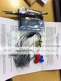
So I read the instructions and all seem clear so I set to it whist at work.
Firstly remove the passenger side trims in the footwell.

With those out of the way you can get to the slabs ecu.its the one on the left with e blue and green plugs(5 plugs on it in total)

Now to start wiring it in, on the grey connector near the back I located the black earth and light green positive.you can see them in the right of the picture
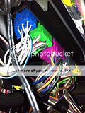
Now i located the sense wire in e green plug, it white with a tiny blue strip on it(the blue strip was on the back for where i was looking in the picture)
Now I used the supplied scotch lock(I will be soldering when the weather is better) all the wires are connected

Now it was to locate the switch by e steering wheel, I have one of those flexible pick up tools and was very handy to get through behind the dash and into the drivers fuse box area
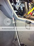
Again I used the flexible pick up stick to pull the switch into the binicle area

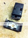
Now to fit into the the empty switch holder, I decided to remove more plastic so the switch could be used in the up and down motion. The blank comes apart and I located the middle and drilled a 7mm hole

Now I used my dremal to remove the plastic from both bits as in the picture.

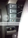
Now it was time to fit the switch blank back together and fit the switch

And the final fitted switch
I'm sure there are little bits I have missed but with David's original instructions its a good fit.
Thanks to David pye for the kit.
It arrived in a few days this is what I got

So I read the instructions and all seem clear so I set to it whist at work.
Firstly remove the passenger side trims in the footwell.

With those out of the way you can get to the slabs ecu.its the one on the left with e blue and green plugs(5 plugs on it in total)

Now to start wiring it in, on the grey connector near the back I located the black earth and light green positive.you can see them in the right of the picture

Now i located the sense wire in e green plug, it white with a tiny blue strip on it(the blue strip was on the back for where i was looking in the picture)
Now I used the supplied scotch lock(I will be soldering when the weather is better) all the wires are connected

Now it was to locate the switch by e steering wheel, I have one of those flexible pick up tools and was very handy to get through behind the dash and into the drivers fuse box area

Again I used the flexible pick up stick to pull the switch into the binicle area

Now to fit into the the empty switch holder, I decided to remove more plastic so the switch could be used in the up and down motion. The blank comes apart and I located the middle and drilled a 7mm hole

Now I used my dremal to remove the plastic from both bits as in the picture.


Now it was time to fit the switch blank back together and fit the switch

And the final fitted switch

I'm sure there are little bits I have missed but with David's original instructions its a good fit.
Thanks to David pye for the kit.
Last edited:
")


