ACE Amber light is on. I have leaking front arm and valve block but I also have the following fault: 41-07 sensor supply voltage out of range. Any idea what could be causing it. Going to try and fix the leaks this week but wanted to see if i can get this fixed as well....
You are using an out of date browser. It may not display this or other websites correctly.
You should upgrade or use an alternative browser.
You should upgrade or use an alternative browser.
Disco 2 ACE Fault 41-07
- Thread starter mad85
- Start date
This site contains affiliate links for which LandyZone may be compensated if you make a purchase.
sierrafery
Well-Known Member
- Posts
- 18,310
- Location
- Arad/Romania
Hi, what scanner was used to retrieve that code? if it was nonocom you can't rely on the code but you can remove the relay, bridge the contact cavities in the fusebox and read live inputs, post the results here and i'll tell you more
Last edited:
Thanks for the help. Can you give me more details on how to bridge the contacts?Hi, what scanner was used to retrieve that code? ifitbwas nonocom you can't rely on the code but you can remove the relay, bridge the contact cavities in the fusebox and read live inputs, post the results here and i'll tell you more
sierrafery
Well-Known Member
- Posts
- 18,310
- Location
- Arad/Romania
Remove the relay and insert a piece of wire in the fusebox as to make a bridge across the two parallel cavities where relay's contact terminals are going 30 - 87

front actuator was leaking badly so was replaced along side new washers. now back to the fault code.
I bridged the contacts but doesnt seem to have made much difference. Also tried to carry out a calibration process for both accelerometers but didnt seem to do anything either. I have taken some photos of my nanocom inputs (engine on, stationary, level ground):


I bridged the contacts but doesnt seem to have made much difference. Also tried to carry out a calibration process for both accelerometers but didnt seem to do anything either. I have taken some photos of my nanocom inputs (engine on, stationary, level ground):
sierrafery
Well-Known Member
- Posts
- 18,310
- Location
- Arad/Romania
Bridging the relay is just for diagnostic purpose, it won't fix anything, might be a wiring issue or bad contact in the plugs at the valve block cos DCV2, PCV and the transducer's values are not OK , troubleshooting is needed but you must understand diagrams and how the system works for that, there is a orange connector near the fusebox innthe engine bay, make sure it's well connected.... here are values from a working system
ACE INPUTS
1. DCVs (both) - .001A
2. Pressure control valve: 0 - .012A
3. Pressure sensor: varies between 16 and 19 but if it's out of that range the transducer is gone
4. Residual pressure: between 3 - 6 Bar but can be higher after the vehicle was driven or the ambient temp is low
5. System pressure: around 6 Bar fluctuating
6. Accelerometers: 0.01
for troubleshooting purpose: the resistance of both DCVs(top of the valve block, DCV1-toward front; DCV2-toward rear)= 2.7 Ohm, pressure control solenoid(on the left side of block) = 5.7 Ohm.
sierrafery
Well-Known Member
- Posts
- 18,310
- Location
- Arad/Romania
Not especially for that. When a fault is present the ECU doesnt close the relay to send the system to locked bars defaut and even if the reay is good if you dont bridge it there will be no power to the system so you can't read live inputs, from these readings i doubt that the transducer is the problem but it's good to rule it out.i understand that bridging the connectors was to rule out a faulty relay
i see, thanks for the explanation. After changing the transducer and checking plugs, the return inputs did not change much. The transducer used is a second hand one, so there is a possibility it may also be faulty?
ACE INPUTS
1. DCVs - 0.00A and .01A
2. Pressure control valve: 0 - .00A
3. Pressure sensor: 32.22
4. Residual pressure: 20.00 (had just been taken out of garage and parked, not a long drive)
5. System pressure: 22.71
6. Accelerometers: 1.34 / 1.42
ACE INPUTS
1. DCVs - 0.00A and .01A
2. Pressure control valve: 0 - .00A
3. Pressure sensor: 32.22
4. Residual pressure: 20.00 (had just been taken out of garage and parked, not a long drive)
5. System pressure: 22.71
6. Accelerometers: 1.34 / 1.42
sierrafery
Well-Known Member
- Posts
- 18,310
- Location
- Arad/Romania
You should measure resistance of the DCV with the 0.00 reading and the PCV and if they are good continuity check on the circuits but for that you have to work by the diagram, dont youhave a spare ACE ECU too cos these used to make tricks as well
sierrafery
Well-Known Member
- Posts
- 18,310
- Location
- Arad/Romania
That would be good, it's plug and play just disconnect the battery before the swap
You should measure resistance of the DCV with the 0.00 reading and the PCV and if they are good continuity check on the circuits but for that you have to work by the diagram, dont youhave a spare ACE ECU too cos these used to make tricks as well
i found an electrical diagram and a description of the plugs. when you say i should measure the resistance of the DCV and the PCV, is it from the plug at the valve block and the ecu?
sierrafery
Well-Known Member
- Posts
- 18,310
- Location
- Arad/Romania
For resistance measure at the solenoid's pins first and if t's OK there then at ECU plug and if at the block is OK and at the ECU not then at C0391, orange plug near the engine bay fusebox, actually check that first to not be a bad contact there
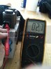
sry for the spoon feeding... so I know resistance is measured between two points. so i should measure the resistance between the pins at the block and the ecu plug? and if that fails, check if there is continuity between ecu and the orange plug and between the block and that orange plug?
sierrafery
Well-Known Member
- Posts
- 18,310
- Location
- Arad/Romania
Similar threads
- Replies
- 6
- Views
- 3K