Freelander 1 PTC Heater TD4

This site contains affiliate links for which LandyZone may be compensated if you make a purchase.

andyfreelandy

Well-Known Member
Posts
5,047
Location
Devon
Having read a few recent posts about overheating PTC (positive temperature coefficient) fuse box on the Freelander 1 TD4, I thought it worth a check in the small fuse box (located on the side of the black box with the engine management module in).

One fuse was melted into place and the other ones had clearly been overheating.

No circuit exists in RAVE, but I found the attached for information.

Worth checking your fusebox !

I am assuming that the 3 x 30A fuses feed the 3 elements in the PTC heater. I have removed the melted one and replaced the other 2 making sure the contacts were tight. I think the failure is overheating contacts where the fuse plugs in rather than an overload by the PTC element. My fuse 3 had welded into the holder and so I carefully removed it and have left it out for now.

Assume that the heater will work at 2/3 power ?? Any one confirm this please. Are the 3 element windings designed to work together and can any one be disconnected without concern, just reducing the power output?
 

Attachments

  • PTC HEATER.pdf
    34 KB · Views: 441
As you suggest, most likely to be corrosion in the fuse holder leading to poor connection leading to heat. I find either silicone spray or silicone grease helps avoid this.

The PDF does suggest three separate elements (labelled ‘3,2,3’ - mistake!) so you should run ok at 2/3 power. If it’s just one element, the fuses would have to be in series, which is unlikely, or parallel, in which case the two left will blow quickly.

You could either re-link the missing fuse with an inline car fuse carrier (ebay) or even get a scrap fusebox from a scrapyard, or online from 1stchoice.co.uk.
 
Hi Andy, do you remember I posted something about a small electrical fire late last year, that was associated with the PTC heater, so I've researched it and became something of an expert on that subsystem, and basically it will / should still work on 2 out of three of the elements, as in the 2/3rds toper you mention.

However, I'd suggest you tread very carefully with this particular circuit!

The circuit is basically, microswitch spurred off the heater operated by a cam on temperature knob, this then allows current to flow to the controlled side of a relay that is closed when the fuel pump is on, so this system cannot receive power without the engine running. the output of that first relay then energises the solenoid of a second relay, located behind the ecu compartment, on the scuttle panel, in the engine bay. This second relay takes its supply from an 80a fusable link connected to the battery by an eyelet connector bolted on the positive clamp, it runs as a single wire underneath the ECU's and into that relay on the scuttle panel. When energised, that relay on the scuttle panel sends power to the little three position fusebox, splitting from a single wire through two splices to three wires witihin the loom running under the ECU compartment. One wire goes to each blade fuse holder, then from that fusebox, power runs into the cabin in 3x wires, the outputs from that fusebox run back along the same loom over the inner wing, up to the scuttle panel and through the bulkhead whereafterwith a wire each for the three heater elements.

80a supply over 3x 30a fuses = 26.6a each circuit. If you remove one fuse, because its melted, you are isolating / disconnecting one of the three heater elemtents, the load on the circuit. But you still have 80 amps available, now going to only a pair, rather than a trio of 26.6a circuits. That 80a is a lot of power and coming from a compromised circuit, I mean why have the fuses melted rather than blown? Heat. Heat generated by current flowing through bad, high resistance circuitry. By removing that one fuse, thus disconnecting one heater element, you are effectivley adding an additional 50% available power to the other two branches on that circuit. I know from my research into PTC that others have issues with the relay on the scuttle panel getting charred, this being the one that controls the supply from the 80a fusable link that feeds the three slot fusebox in which you have a melted fuse.

An 80a circuit is a lot of juice, its a full kilowatt with an alternator running at nominal 13 volts.

If you have a fuse melted in the PTC fuse box, you really ought to replace that box, check the PTC relay on the bulkhead, clean up all the contacts from battery terminal --> fusable link --> wire from fusable link to relay --> wires from relay to splices --> splices to fusebox --> fusebox to PTC heater.

You need to do that to make sure you dont continue to have the resistance turn the juice into heat and go melty / smokey / firey burny.

Personally I've mentally named the PTC as Pyro Technic Circuit.

Not meaning to be all doom and gloom, I know its far too easy for us jocks to be portrayed as:
images


But it is a high current circuit on a ~20 year old vehicle, that is starting to show signs of its age, and I'd really rather you thoroughly check out your 1kw electric heater, that uses about the same power as one bar on an electric fire, so it functions more like this sort of electric fire:
dimplex-yeominster-freestanding-electric-radiant-bar-fire-yeo20-a0d.jpg

than this type of electric fire:
1762768.jpg


Remember when mine went I had started the car to let it heat up before driving it, and went back inside, it was only by luck that I went out to put something in the car to take with me, and I could hardly see the car for smoke. While I was lucky enough to catch mine, I was probably only a couple of minutes away from mine going up like the one in that picture above.
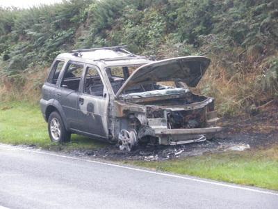
 
The issue is with corrosion of the fuse blades. Unfortunately the fuses are made of aluminium, which does corrode on its surface from the moment it's made. When the fuse is pushed into the fuse holder, this surface corrosion is cut through, so the connection is made. However after many years of heating and cooling, passing current and so on, the connection begins to fail as corrosion sets in. At this point the connection resistance increases, which generates heat, lots of heat. The more heated the connections get, the higher the resistance, and so the cycle continues, until the connection breaks, or the fuse box goes up in smoke.

The best prevention to this, is simply to replace the fuses annually, and use silicone grease on the fuse blades to keep corrosion at bay.

Hope this helps.
 
Thanks for all the above input. I have a spare fuse box but can't see how to extract the small fuse holder connections at the moment. Must be a pin to oush in somewhere!!

For now I'll leave fuse out, only 2 elements energised should be fine. A supply of 80a is further fused down to 30A each element. Power is drawn by the resistance of the element attached and whether the feed is fused at 80A or 100A the current drawn by each remains unchanged.

I may see how the heater works with all fuses removed. I am always amazed by the dip on the headlights when you switch the heater control up!!

I see the F2 had a recall over fire risk on the ptc heater circuit activating when it shouldn't.
 
yeah .. some good info in the above posts
i've never worried about the ptc heater
but now will check the fuse holder condition n replace the fuses
as is .. i remove the cab relay once the outside temps are above 10c
``````````````
a.t.b.
 
I have had problems with my PTC so i did a few checks after finding this info i have got voltage going to the PTC but it is not getting warm at all so it takes ages for the tempature to get up so from what i can gather i will need another unit are they simple to replace or is it a radiator out job . must say fuses are fine i have checked the relay and all is fine as i said geting 14.48 volts to the PTC
 
Mine near torched the freelander a while ago, but I have since done a thermostat on it, and with the new thermostat, the vehicle has hot air coming out of the heater within a few minutes. So to solve the motor being cold, it might be the lesser of two evils to do a thermostat rather than dashboard out to fix the PTC?
 
Back in early 2000’s LR did a recall programme on the ptc, I believe it was liable to short and overheat from condensation dropping on to it from a/c condenser, so it is an item to look after, not neglect
The first action by dealers was to remove fuses, until they had parts for action in stock
 
@teddywood1 To double isolate it, there is an 80amp fusable link mounted to the innerwing under the forward edge of the engine bay fusebox, this comes to an eyelet bolted to the live terminal on the battery, disconnect that. As it is with the 3x 30amp fuses removed, the sequence of switches/relays that ultimately activates the PTC is still sending power to the little fusebox.

The system is set up using something of a dieing art - electromechanical engineering, nowadays most stuff like this is just programmed into a microcontroller, however this is done with sequential switches and relays, quite cute and quaint, but the specifics are:
  • The first switch is in the dashboard, operated by a cam lobe on the heater control, when the temperature is moved to hot, 1 o'clock onwards, this sends power as the signal to the first relay (logic thusfar - occupants want more heat)
  • The first relay, located in the cabin, receives its control signal from the switch in heater control, and on it's controlled side, opens an earth path for the signal side of second relay (logic thusfar - occupants want more heat enabling next relay which will check if engine running to power heater)
  • That second relay, which is located on the bulkhead in the engine bay beside the ECU box ventilation corrugated tubes to the scuttle panel, gets its control signal live from the signal to the fuel pump relay. (when the switch is closed, the first relay is energised, and the earth path for this relay's coil is created). This second relay, once actuated/controlled links the 80amp fusable link to the 3x 30amp fuses (logic thusfar - occupant wants more heat AND engine running THEREFORE send power)
  • After passing the logic tests above, ie occupants want more heat and the engine is running, the second relay is energised. The second relay supplies controls power from the battery, via the 80amp link, to the relay, then from the relay via a thick(er) single black wire that runs under the ECU and Fuseboxes in the engine bay, this then splices to three thinner wires under the engine fuse box, and they become the feeds for the aforementioned fusebox.
Here is the potential "gotcha!" - with the fuses removed you've still got power flowing from the battery, via an 80A fusable link, across that relay on the bulkhead, and into the three fuse fusebox fuses supply side! Even with the 3x30A fuses removed, you are still sitting with a kilowatt* of potential power running around redundant, and mostly hidden wiring in your engine bay!
* the 80 amp fusable link when operating at healthy alternator / battery voltage of 13.2v x 80amps = 1,056watts
  • Assuming normal PTC operation, ie: fuses reinstated, those three fuses then feed the three wires to the heater elements. Those wires, again, run under engine bay fusebox, going into the bulkhead, behind the dash and to the drivers side to feed the PTC elements.
Not wanting to be a nagging nanny-goat, but if you are going to inhibit the PTC system pending future maintenance, I'd suggest you disconnect the battery eyelet that feeds the power to the second relay that feeds the 3x fuses that you've yoinked, thus removing a kilowatt of power from needlessly lingering in the redundant, and hidden, PTC wiring.
 
Last edited:
Hi. I find this topic very interesting.
I have a 2005 td4 facelift.
I have looked for the 30a fuses and I cannot find them, where are they?
My silicone oil spray has a pictogram that is flammable, is it not dangerous to apply it to the fuses?
Thank you.
 
The fuses are in the little box that the yellow arrow is pointing at in the picture below:
hippo-engine-png.190458

If you don't have 3x 30A fuses in there it means you have either a heated front windscreen and or a fuel-burning heater.
 
thank for the info when it gets a bit warmer i will investigate more my memory isnot what it was following a small stroke but the wife reminded me that before all this coldness in the heater i had a new battery now i am wondering if that has anything to do with it.
 
well i have checked the fuses and none are coroded they pull out and fush in fine i took the rubber protector of the relay then because my relay tester did not have the right holes in it to test i took the top off and got the wife to put on the ignition and it closed she also started the motor and it kept closed so all seem to be working but it still takes time to warm the engine up where before it heated up quickly so i got my tester for the anitifreeze and it did not come up to what it should , so i thought emty the header tank and just put the antifreez in but when i look at the head tank it had cracks all the way around it so i am awaiting the delivery of a new one, my thinking is with not much anti freeze in the some of the water could be freezing and thats why it is taking a long time to heat up we will see once I have the new header tank.but while looking around the battery just in case i missed something i found this wire with a plug on the end does anybody know what it is to just below it along side of the battery on the wing side there was another one but that was pluged into anothe wire my freelander is a 2006 hse auto
 

Attachments

  • DSC_0486 (2).JPG
    DSC_0486 (2).JPG
    120.5 KB · Views: 141
so i got the relay which is in front of the scuttle panel and this it the one in the picture but where is the fuse for it
 

Attachments

  • DSC_0485 (6).JPG
    DSC_0485 (6).JPG
    176.9 KB · Views: 137
Back
Top