OK. The definitive explanation of how to bodge a freelander early style brake switch. Even if you dont biodge, getting it apart is good because its a simple beast at heart and if it is not good, its pretty obvious, which tells you what you need to buy.
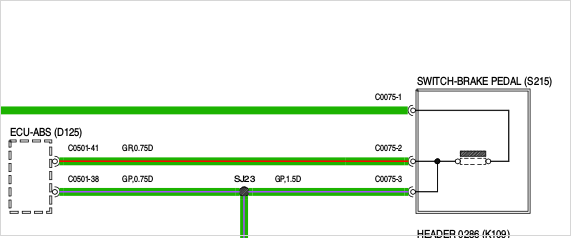
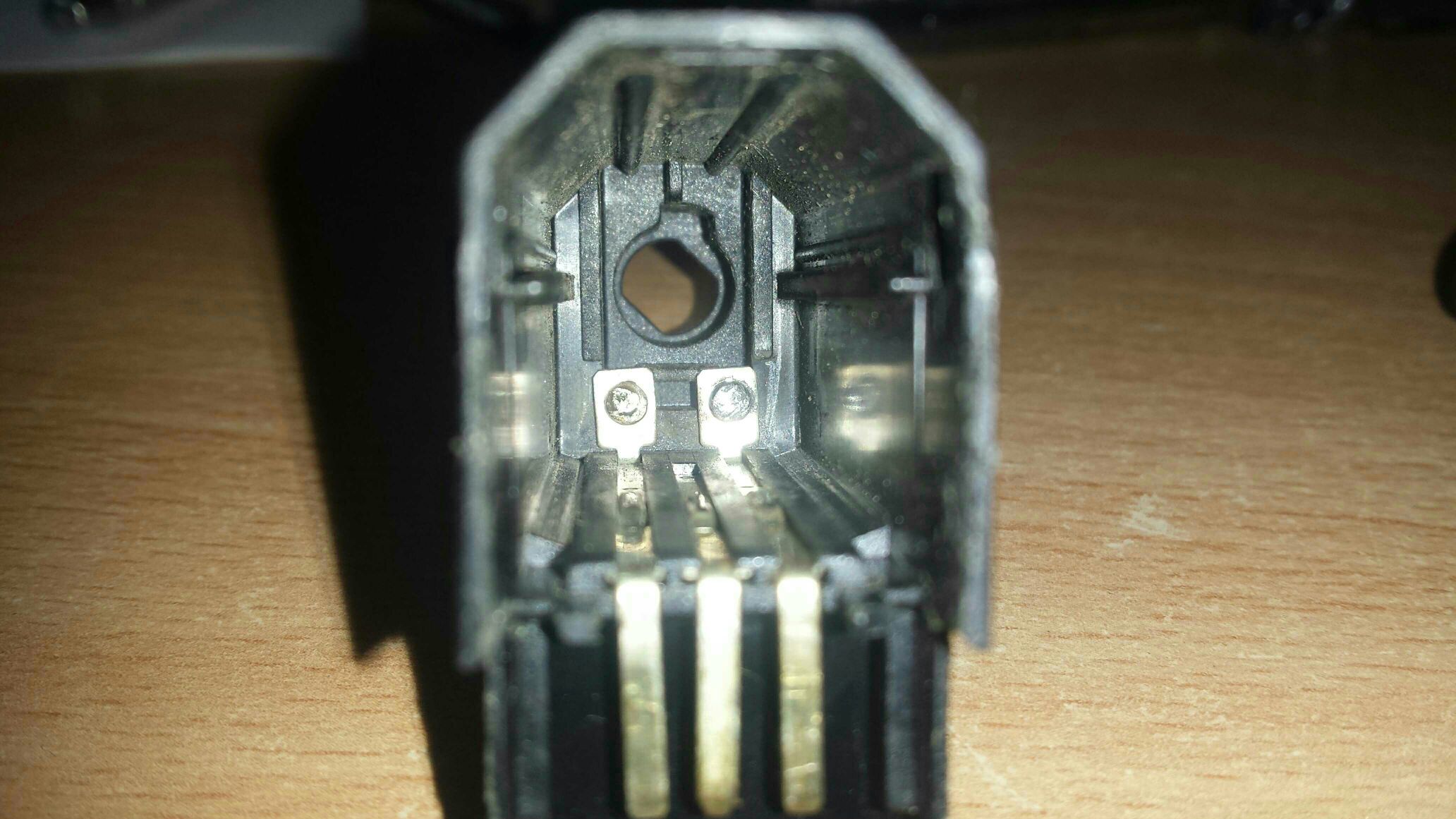
What you should see with a continuity tester, is that the outer two pins show connectivity, until you press the plunger. Then the connectivity should break. The center pin is connected to one of the other two at all times. Unless you push the plunger to impractical positions.
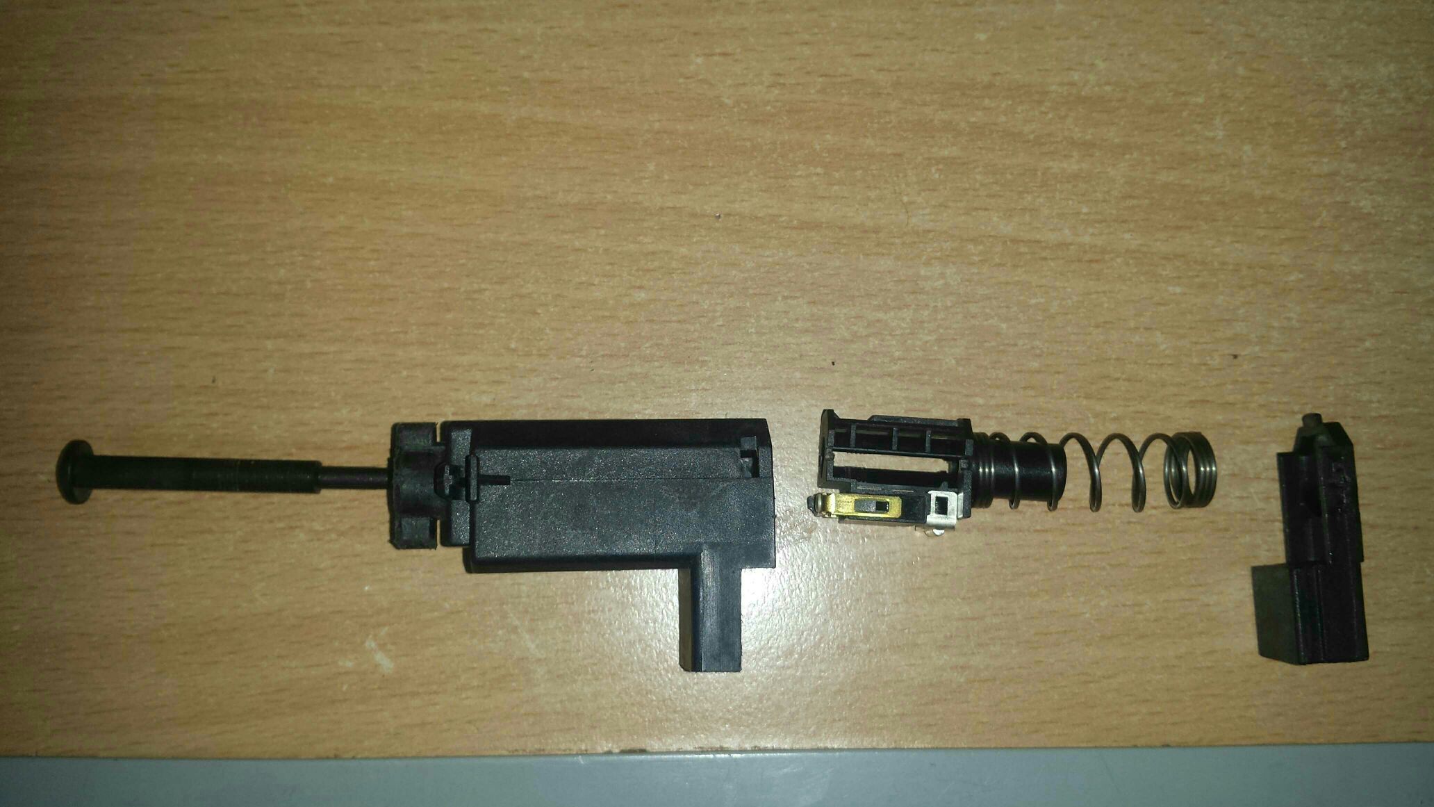
First of all how you get the little sucker apart.
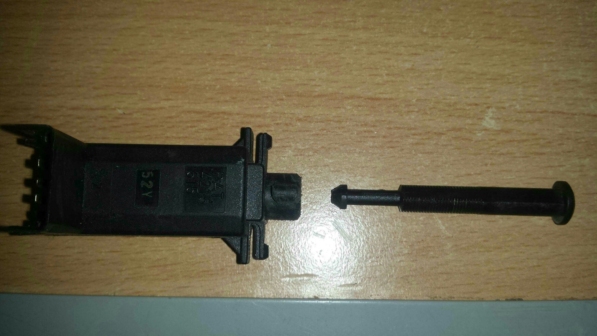
Pull off the end part
sideways using two tiny screwdrivers to lever the outer case clear of the retaining lugs.
The only ping####it at this point is the large spring that actually operates the main brake switch.
So be aware its going to do a jack-in-the-box as you slide the end cap over the plug contacts.
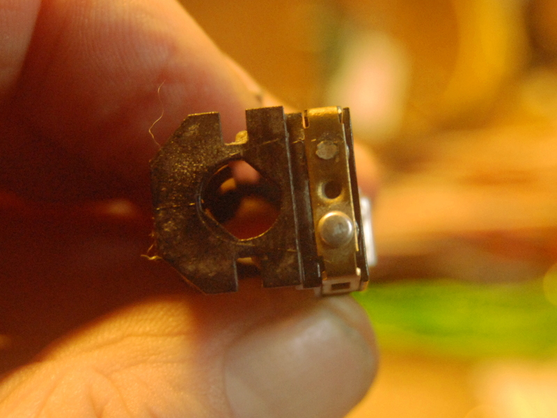
Now you can see the more useless part of the switch. Nothing is revealed further until that damned plunger comes out.
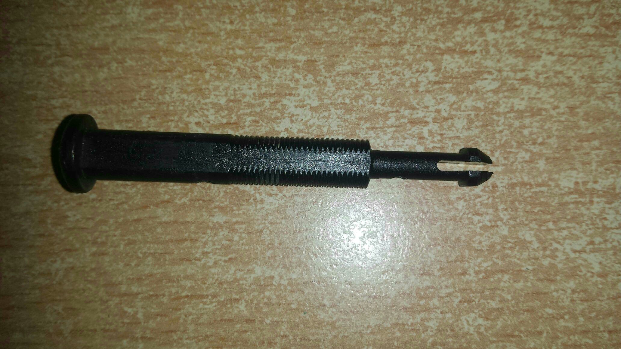
Push the plunger right IN until you can see the tip. There is a screwdriver slot in it as to get it out the two halves have to be pushed hard together at the bottom of a deep hole.
We used a bit of an old telescopic aerial of lord knows what - me mate collects this stuff - he's still an electronic engineer.
You need a bit that is small - not to fit over the whole of the plunger tip, but just big enough to get it on the taper and compress it. .
Pull the plunger as far as it will go first. It won't come out. Then apply the tube HARD and Pull HARD and it should pop out. Satisfying moment.
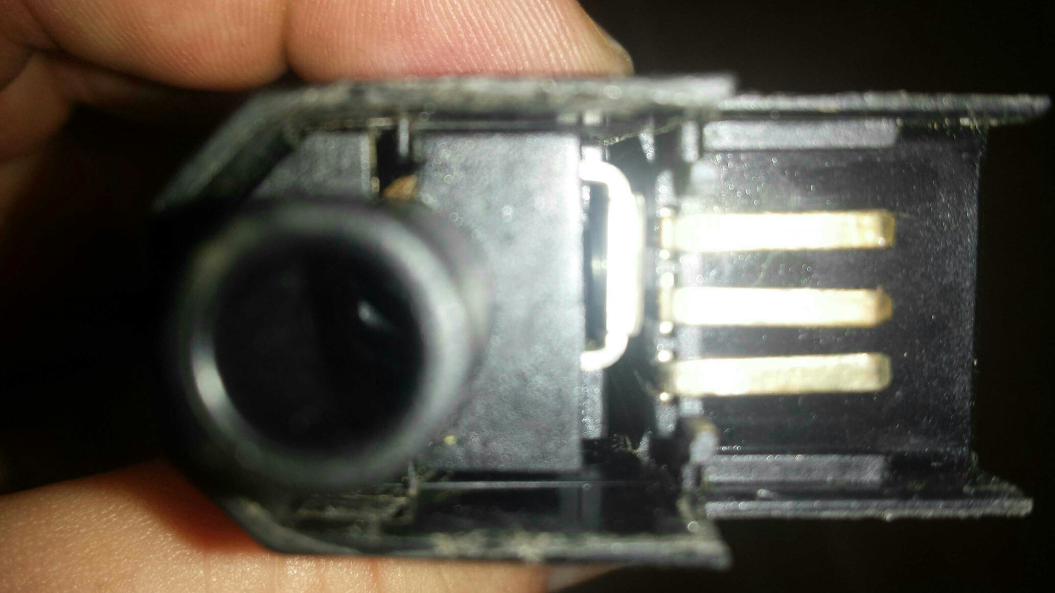
The contacts that go to the plug - all three - can now be gently slid up the body of the switch until they are out, and then inspected.
In my case one had snapped off completely and was lying loose inside.
No, I dunno how it was working either.
I didn't bother removing the centre pin as this was working.
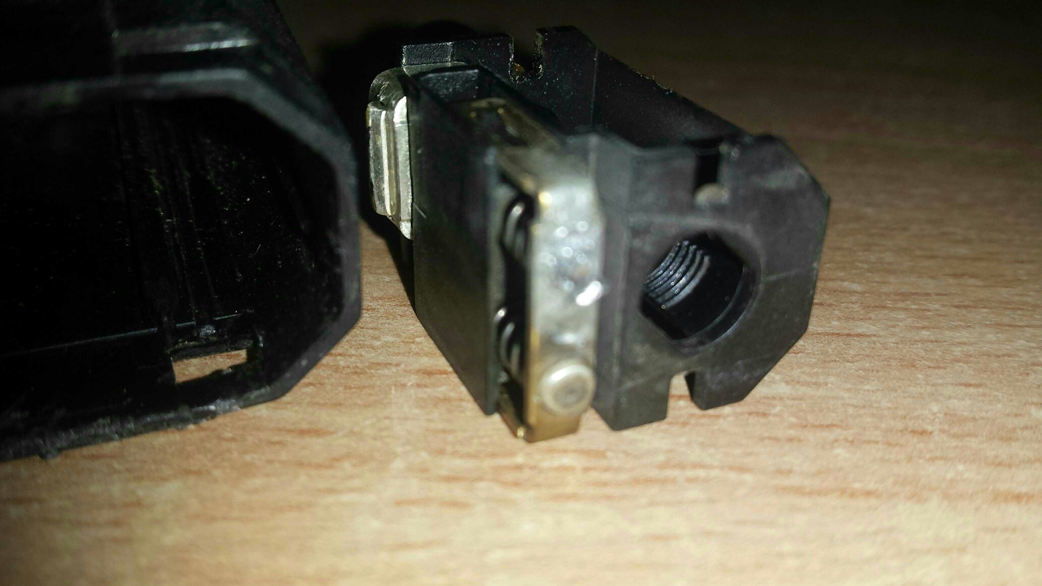
Now you can see the state of the fixed contacts, time to look at the moving ones.
And another 'oh ****' moment
Yep, one contact had sheared off completely.
Fixing the bar steward
I am not going to completely detail how I fixed all this: If you do model engineering, electronics and can handle a soldering iron you will know, if you don't, don't even think about doing what I did.
Briefly I soldered the broken fixed contact back together and filed away at the solder blob till it fitted into its slot and was more or less at the correct height.
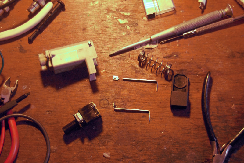
Then I removed the brass contact carrier on the moving part of the switch carefully retaining two more ping####its and got that into a vice where me mate drilled out the broken contact.
Then we stripped an old car relay for a silver contact on some bronze shim and got it as cleaned up as possible. It was way proud when laid on the old contact carrier, but we did our best, and I soldered it from the reverse side.
Remember, although two sides of the switch can break the contacts,
it's only necessary for one to do so to stop the brake lights being on all the time. This whole switch looks to have been designed by a dumb apprentice who was really not thinking at all.
Anyway once all the contacts were soldered back together it was time to try and normalise the heights a bit with a diamond needle file and some 620 grade emery, which is what we had. I bent the contact carrier a bit so it was lopsided to equalise hights a bit more and assembled it back with the two smaller springs.
A quick partial assembly without the plunger showed contact was being made by default, and that lifting the plastic slide up a bit broke it. It looked like the switch should work.
Next I pushed the plunger in a little way to locate the slider, and refitted the top part. The switch was now reassembled. Retesting showed that the centre contact pin was always connected to one of the outers, and that the two outers were connected until the plunger was pushed in against the spring a little. Hurrah!
Refitting has been covered elsewhere, but for completeness here goes.
In order to fit the thing at all, the plunger may need to be ratcheted in a fair bit. Also on my car with the cruise control sensor there are a lot of wires in the way of getting the damned thing in, but the important thing is to get it located, pushing it in
with the brake pedal depressed and twist it 15 degrees clockwise to lock it. Then releasing the brake pedal slowly you hear a few clicks of the ratchet till it self adjusts the plunger correctly.
The turn the ignition on. The two amigos don't go out, so start the engine, and then press the brake pedal when your mate yells 'brake lights working!' and the two amigos go out.
And you do a small war dance round the drive to the consternation of the neighbours.
Was this worth doing?
Absolutely NOT. with a new (old style) switch at less that £15 from most places , the time and skill it took and the necessity to actually have the tools, unless you are an electronic or electrical engineer with time on your hands and no money (I am) you shouldn't even think about it.
HOWEVER I need this car RIGHT NOW with working brake lights, its Sunday and no parts stores are open, and I reckon the repair is really really sound and will last long enough to get a spare switch off Ebay or whatever.
And heck, I wasn't doing anything else important anyway.